
Material lifting device for on-site remixer

A compound mixer and aggregate technology, which is applied in road repair, roads, roads, etc., can solve the problems of the occupancy of the lifting device, affecting the compactness and large space of the whole machine parts, and achieve the effect of saving the layout space.

Active Publication Date: 2020-08-11
JIANGSU JITRI ROAD ENG TECH & EQUIP RES INST CO LTD
View PDF17 Cites 2 Cited by
  • Summary
  • Abstract
  • Description
  • Claims
  • Application Information

AI Technical Summary

Problems solved by technology

[0004] The purpose of the present invention is to provide a material lifting device for an in-situ remixer to solve the problem that the material lifting device in the prior art takes up a large space and affects the compactness of the parts of the whole machine

Method used


Image

  • Material lifting device for on-site remixer
  • Material lifting device for on-site remixer
  • Material lifting device for on-site remixer

Examples


Embodiment Construction

[0033] The following will clearly and completely describe the technical solutions in the embodiments of the present invention with reference to the accompanying drawings in the embodiments of the present invention. Obviously, the described embodiments are only some, not all, embodiments of the present invention. Based on the embodiments of the present invention, all other embodiments obtained by persons of ordinary skill in the art without making creative efforts belong to the protection scope of the present invention.

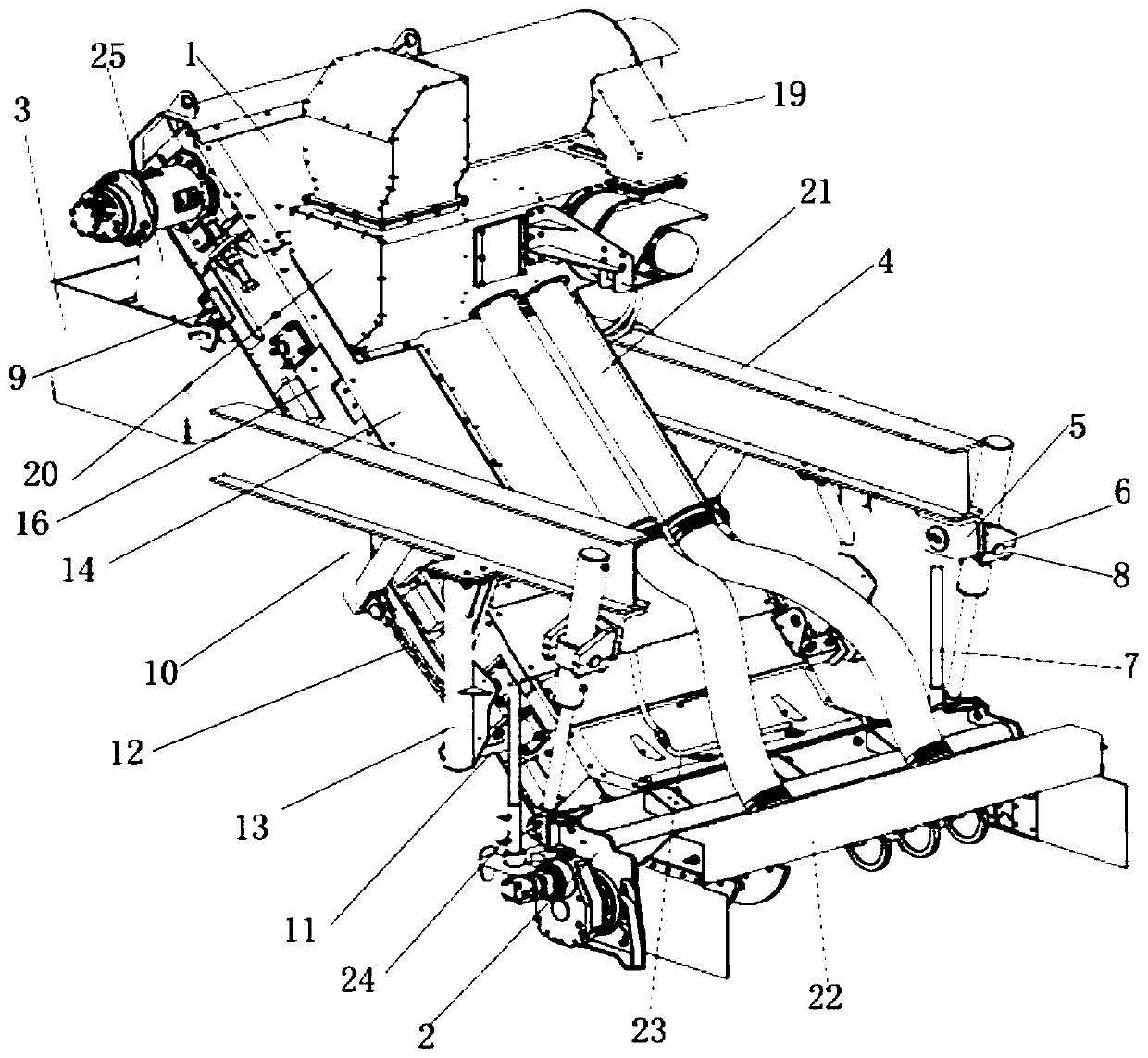
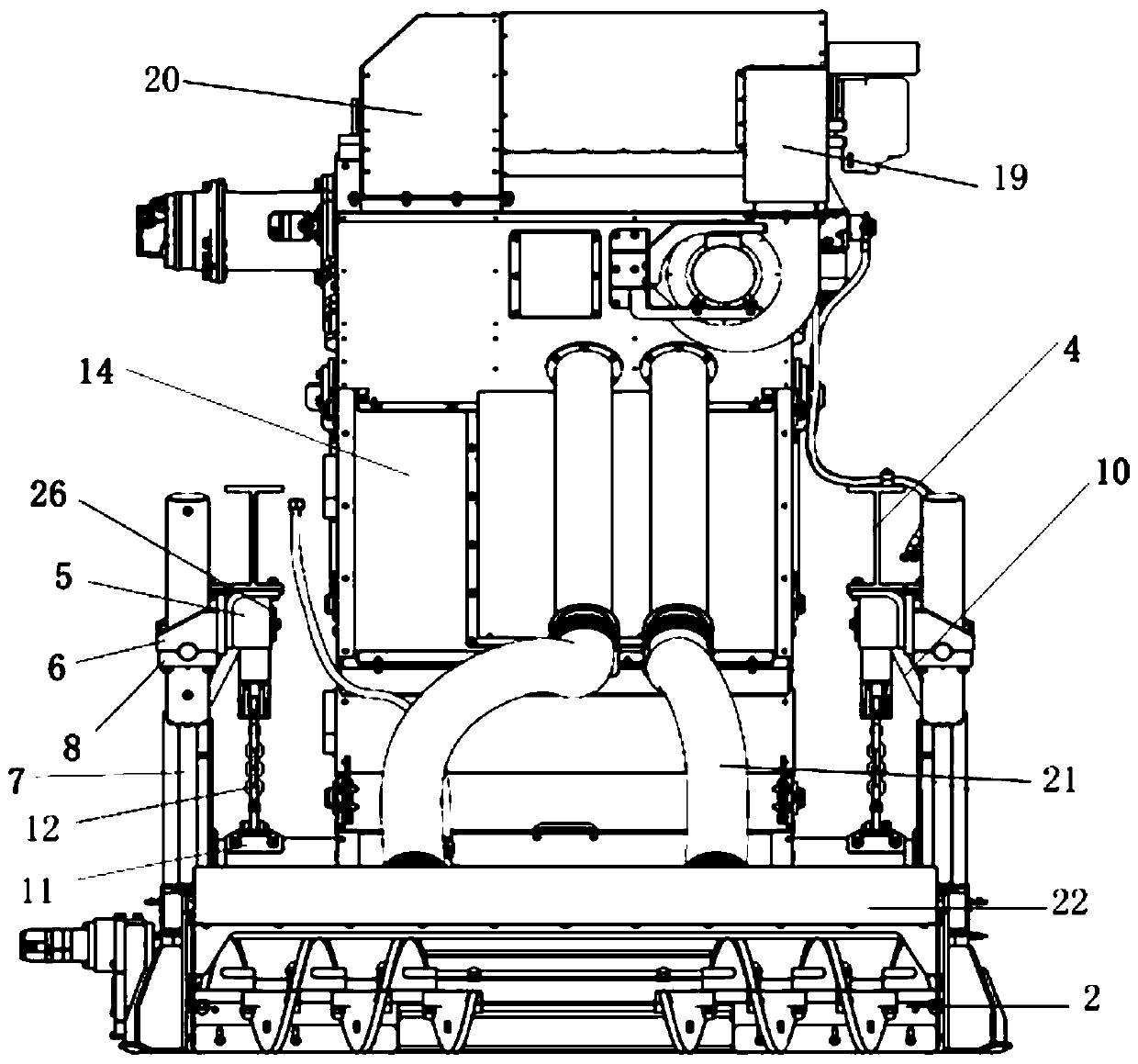
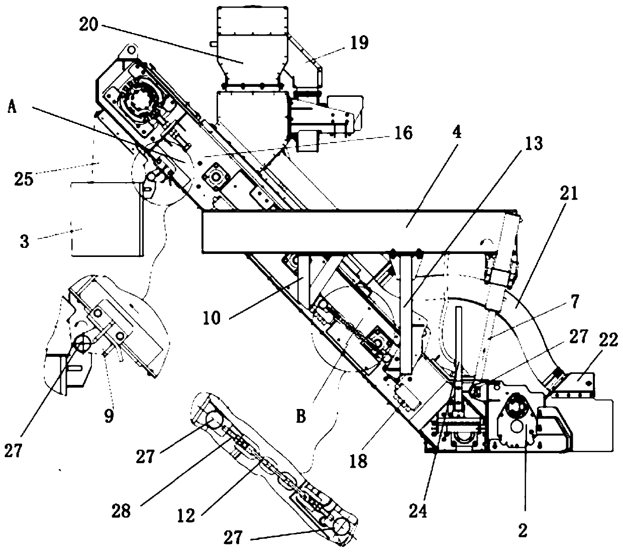
[0034] Such as Figure 1 to Figure 4 As shown, it is a material lifting device for an in-situ remixer provided by an embodiment of the present invention, comprising a material lifting device main body 1, an aggregate 2 and a mixing tank 3, and the aggregate 2 is placed at one end of the material lifting device main body 1, And the discharge port of the aggregate 2 is connected with the feed port of the main body 1 of the material lifting device, the mixing cyl...


PUM


Abstract

The invention discloses a material lifting device for an on-site remixer. The material lifting device comprises a material lifting device main body, an aggregator and a mixing cylinder, and an asphaltmixture is gathered into a material pile through the aggregator, then enters the material lifting device main body, is conveyed to the mixing cylinder and is mixed; lifting oil cylinders are arrangedon the two sides of the material lifting device main body, one ends of the lifting oil cylinders are connected with the aggregator through pin shafts, and the other ends of the lifting oil cylindersare connected with oil cylinder rotating bases through supporting plates. Sliding rotating seats are arranged on two sides of one end, close to the mixing cylinder, of the material lifting device mainbody, and are connected with the mixing cylinder through pin shafts; and chain supports and chains are arranged on the two sides of the material lifting device main body, one end of each chain is connected with a triangular support on a vehicle frame through a pin shaft, and the other end of each chain is connected with the corresponding chain support through a pin shaft. By adjusting a multi-degree-of-freedom lifting structure, under the condition of lifting the same height, the rotating angle of the material lifting device can be reduced, and the arrangement space of the whole machine is saved.

Description

technical field [0001] The invention relates to the technical field of road engineering machinery, in particular to a material lifting device for an in-situ remixer. Background technique [0002] The in-situ remixing machine is the key link in the construction of the asphalt pavement hot-in-place recycling unit. Before paving the asphalt mixture on the road surface, it is necessary to use a lifting device to add the original road asphalt mixture after milling to the stockpile. In the new asphalt mixture, it is lifted to the mixing tank for uniform mixing to prevent the segregation of the asphalt mixture, which will affect the construction quality of the road surface. [0003] After the construction of the in-situ remixer is completed, the lifting device needs to be lifted to a height greater than 350mm from the ground to ensure good trafficability of the vehicle. The existing lifting device includes a rotary lifting device and a sliding lifting device. The rotating angle of...

Claims


Application Information

Patent Timeline
IPC IPC(8): E01C19/10
CPCE01C19/1004E01C19/1072
Inventor 理俊杰张江勇王贵张陈赵书祥陆平樊丽丽张青国
Owner JIANGSU JITRI ROAD ENG TECH & EQUIP RES INST CO LTD
Learn More