
Calculation method of pressure behind stopper mouth considering water injection start pressure gradient

A technology of starting pressure gradient and calculation method, which is applied in the fields of instrumentation, earthwork drilling, design optimization/simulation, etc., can solve the problem that the oil reservoir cannot realize fine layered injection, etc., so as to improve the development effect and increase the longitudinal production of the reservoir. degree, the effect of increasing the degree of use

Active Publication Date: 2021-01-26
SHENZHEN LOTUT INNOVATION DESIGN CO LTD
View PDF16 Cites 0 Cited by
  • Summary
  • Abstract
  • Description
  • Claims
  • Application Information

AI Technical Summary

Problems solved by technology

[0008] The object of the present invention is to provide a method for calculating the pressure behind the plug mouth considering the water injection starting pressure gradient. This method for calculating the pressure behind the plug mouth considering the water injection starting pressure gradient is used to solve the problem that multi-layer water injection development reservoirs cannot achieve fine layered distribution. note question

Method used


Image

  • Calculation method of pressure behind stopper mouth considering water injection start pressure gradient
  • Calculation method of pressure behind stopper mouth considering water injection start pressure gradient
  • Calculation method of pressure behind stopper mouth considering water injection start pressure gradient

Examples


Embodiment 1

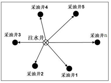
[0105] (1) A typical injection-production well group in a block of Daqing Oilfield was selected as the research object. The well group contained 1 water injection well and 4 oil production wells, and the water injection well group was divided into 7 injection-production intervals. See the attached figure 2 . The basic parameters of water injection wells and production wells in typical injection well groups are shown in Table 1.

[0106] Table 1 Basic parameters of typical injection-production well groups

[0107]

[0108] (2) Calculate the proration pressure difference of the water injection well in each injection-production section.

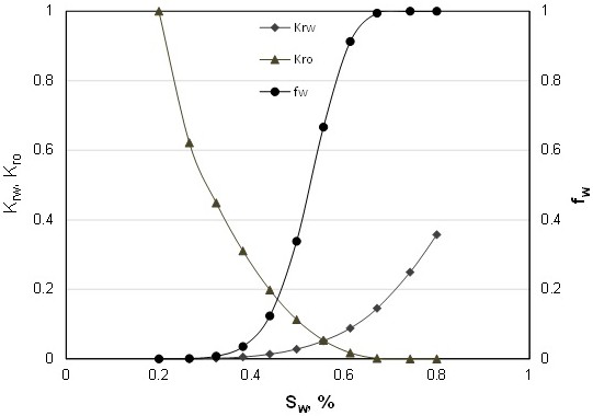
[0109] Specifically, the total injection volume designed for water injection wells is 100m 3 Based on / d, the equivalent well spacing between water injection wells and production wells, the average water content at the production end of the production wells in the well group, the relative permeability of the water phase in the injection-p...


PUM


Abstract

The invention relates to a blanking plug nozzle back pressure calculation method considering water injection starting pressure gradient. The method comprises the following steps that a typical injection-production well group is selected as a research object, the typical injection-production well group comprises one water injection well and n oil production wells, and the n oil production wells aredispersed around the one water injection well; the flattening thickness of a jth injection-production interval of the typical injection-production well group is calculated; the equivalent well distance between the water injection well and the oil production wells in the typical injection-production well group is calculated; the average absolute permeability of the jth injection-production interval of the typical injection-production well group in each direction is calculated; the oil-water two-phase relative permeability of the injection-production interval of the typical injection-productionwell group in each direction is calculated; the injection allocation amount of the jth injection-production interval of the water injection well is calculated; the production allocation pressure difference of the water injection well in each injection-production interval is calculated; the additional starting pressure difference of each injection-production interval is calculated; and the blanking plug nozzle back pressure of each injection-production interval of the typical injection-production well group is calculated. According to the method, the interlayer heterogeneous contradiction of the multi-oil-layer water injection development oil reservoir can be effectively relieved, the water absorption profile is adjusted, and fine layered injection allocation is achieved.

Description

technical field [0001] The invention relates to the technical field of layered injection of water injection wells in oil field production, in particular to a method for calculating the pressure behind a plug nozzle considering the pressure gradient at the start of water injection. Background technique [0002] When most water drive oilfields enter the middle and late stages of development, the heterogeneity of the reservoir becomes more and more serious with the flushing of water injection. In the process of water flooding to develop multi-layer reservoirs, it is necessary to consider interlayer heterogeneity and interlayer contradictions, finely divide flow units, and formulate individualized injection allocation schemes. At present, the quantitative water injection method of water injection wells cannot truly achieve layered and quantitative water injection. The main reason is that the injection-production system is quantitative at the injection end but not at the producti...

Claims


Application Information

Patent Timeline
Patent Type & Authority Patents(China)
IPC IPC(8): E21B49/00E21B43/20E21B43/14E21B43/30E21B47/06G06F30/20G06F119/14
CPCE21B43/14E21B43/20E21B43/30E21B47/06E21B49/00G06F30/20G06F2119/14
Inventor 周晓峰魏建光李江涛周润楠李继尧李颖雪
Owner SHENZHEN LOTUT INNOVATION DESIGN CO LTD
Learn More