
Intelligent bicycle lighting device with a wind power generation function

A technology of smart bicycles and lighting devices, which is applied to wind power generation, lighting devices, lighting device components, etc., can solve the problems of stopping lights and turning off the car, laboriousness of the car, etc., and achieves the effect of diverse functions and ingenious structure

Pending Publication Date: 2020-08-11
肖年盛
View PDF0 Cites 1 Cited by
  • Summary
  • Abstract
  • Description
  • Claims
  • Application Information

AI Technical Summary

Problems solved by technology

[0003] The technical problem to be solved by the present invention is to provide a smart bicycle lighting device for wind power generation, which can effectively solve the problems that the traditional wheel-driven generator is more laborious and the lights are off when the car is powered by the generator. The car lock provides electric energy support, combined with the car smart car lock to intelligently control the lighting device, it has the characteristics of ingenious structure, convenience and practicality, and various functions

Method used


Image

  • Intelligent bicycle lighting device with a wind power generation function
  • Intelligent bicycle lighting device with a wind power generation function
  • Intelligent bicycle lighting device with a wind power generation function

Examples


Embodiment Construction

[0026] The following descriptions of the various embodiments refer to the accompanying drawings to illustrate specific embodiments in which the present invention can be practiced. The directional terms mentioned in the present invention, such as up, down, front, back, left, right, inside, outside, side, etc., are only ways of referring to the attached drawings. Therefore, the directional terms used are used to illustrate and understand the present invention, but not to limit the present invention. In the figures, structurally similar units are denoted by the same reference numerals.

[0027] The technical solutions and beneficial effects of the present invention will be clearer and more definite by further describing the specific embodiments of the present invention in conjunction with the accompanying drawings.

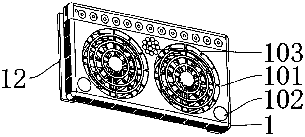
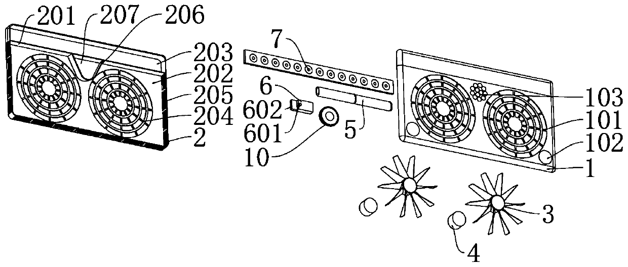
[0028] See attached Figures 1 to 6 , the present invention includes a front cover 1 and a rear cover 2 which cooperate with each other. Cooperating impeller 3 an...


PUM


Abstract

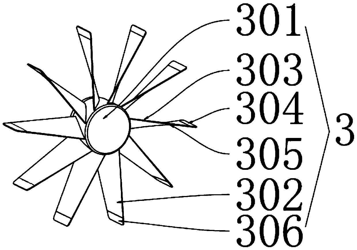
The invention discloses an intelligent bicycle lighting device with a wind power generation function. The device comprises a front cover and a rear cover which match each other, the inner side of therear cover is divided into a power generation cavity and a sealing cavity through a first sealing partition plate, a plurality of sets of impellers and generators which match each other are arranged in the power generation cavity, and one impeller or two coaxial impellers is or are arranged; a plurality of parallel shaft ventilation nets I matching the impeller is arranged on the front cover; a plurality of parallel shaft ventilation nets II matching the impeller is arranged on the rear cover; vertical shaft ventilation nets matching the impeller are arranged on the left side wall and the right side wall of the rear cover; the impeller comprises a hub and a plurality of blades arranged on the hub. The ends, close to the hub, of the blades are parallel wind force bearing parts, the other ends of the blades are vertical wind force bearing parts, transition parts are arranged between the parallel wind force bearing parts and the vertical wind force bearing parts, the transition parts arein a twisted twist shape, the blades can be blown by parallel wind force and vertical wind force at the same time, and the wind driven generator has the advantages of being ingenious in structure, convenient to use, practical and multifunctional.

Description

technical field [0001] The invention relates to a bicycle lighting device, in particular to an intelligent bicycle lighting device for wind power generation. Background technique [0002] At present, the lighting device on the bicycle mainly uses friction power generation, that is, the wheels drive the generator to rotate to generate electricity, and the generator provides electric energy lighting for the lights. This method has some disadvantages. First, the generator needs the wheels to rotate, which will give Wheels bring a certain amount of resistance, and using wheels to generate electricity for lighting at night will obviously take a lot of effort. Secondly, this way of generating electricity with wheels will stop the car and turn off the lights. When the light is insufficient and lighting is needed, the car cannot keep driving. It is obviously not very convenient to turn off the lights as soon as you stop. Contents of the invention [0003] The technical problem to...

Claims


Application Information

Patent Timeline
Patent Type & Authority Applications(China)
IPC IPC(8): F21S9/02F21S9/03F21S9/04F21V19/02F21V23/00F21V23/04F03D9/11F03D9/32F03D3/00F03D3/02F03D3/06B62J6/06B62J6/20B62J6/028B62J3/12F21W107/13F21Y115/10
CPCF21S9/026F21S9/03F21S9/043F21V19/02F21V23/003F21V23/02F21V23/0464F03D9/11F03D9/32F03D3/002F03D3/02B62J6/06B62J6/20B62J6/028B62J3/12F21W2107/13F21Y2115/10F03D3/062Y02E10/74Y02E10/728Y02E70/30
Inventor 肖年盛
Owner 肖年盛
Learn More