
A fresh air system built inside the range hood and on the door cover

A fresh air system and range hood technology, applied in the field of kitchen air purification, can solve problems such as poor smoke exhaust effect of range hood, insufficient fresh air supply, and indoor odor, etc., to achieve better smoke exhaust effect, short air circulation path, and high power consumption. demand reduction effect

Active Publication Date: 2021-10-12
王庆虎
View PDF5 Cites 0 Cited by
  • Summary
  • Abstract
  • Description
  • Claims
  • Application Information

AI Technical Summary

Problems solved by technology

[0006] Based on the above-mentioned defects of the prior art, the present invention proposes a fresh air system built inside the range hood and on the door cover to solve the problems of poor smoke exhaust effect, insufficient fresh air supply and indoor odor of the existing range hood

Method used


Image

  • A fresh air system built inside the range hood and on the door cover
  • A fresh air system built inside the range hood and on the door cover
  • A fresh air system built inside the range hood and on the door cover

Examples


Embodiment 1

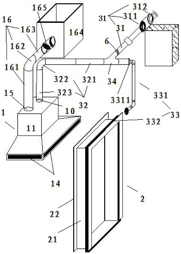
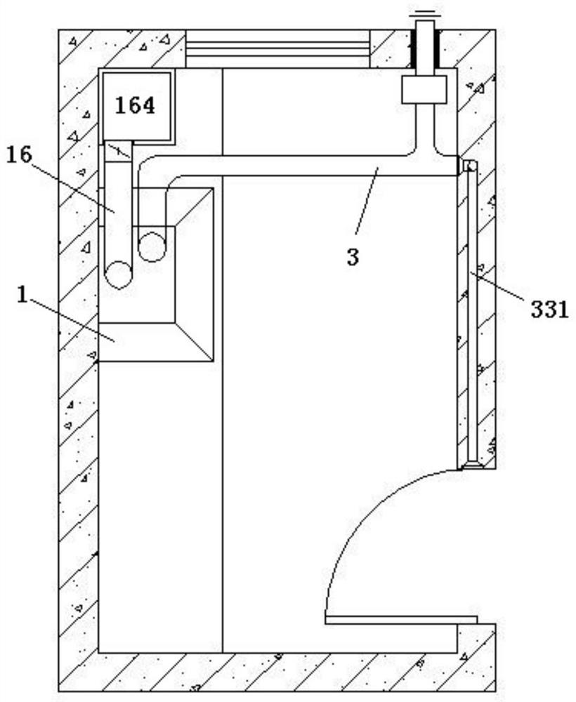
[0034] like figure 1 , as shown in 3-10, a fresh air system built into the interior of the range hood and on the door cover of the present invention includes a kitchen range hood 1, a kitchen door cover 2 and a fresh air duct 3, and the fresh air duct 3 is provided with a fresh air fan 6, The fresh air duct 3 includes an air inlet pipe 31 , a range hood fresh air duct 32 and a door cover fresh air duct 33 . In this embodiment, as figure 1 As shown, the fresh air fan 6 is only provided in the air inlet duct 31 . One end of the air inlet pipe 31 is sequentially provided with an outer wall sealing sleeve 311 and a rainproof ventilation valve 312 from the inside to the outside. An air filter device 341 is also provided on the fresh air tee 34 connected with the air inlet pipe 31 . The fresh air duct 32 of the range hood is composed of a horizontal pipe 321 , a curved pipe 322 and a vertical air transmission pipe 323 . The door cover fresh air duct 33 includes an L-shaped pre-e...

Embodiment 2

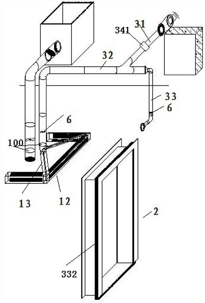
[0049] like Figure 2-10 As shown, in this embodiment, the fresh air fans 6 are respectively arranged in the vertical air duct 323 and the L-shaped embedded wall air duct 331 . Other structures are the same as those in Embodiment 1, and are not described in detail here.

[0050] In this embodiment, the fresh kitchen air enters the room through the rainproof and ventilating valve 312 in the outer wall, and the air duct of the airtight casing 311 of the outer wall enters the room, is filtered by the air filter device 341, and is divided into two paths through the fresh air duct, and is respectively transported to the fresh air of the range hood. Duct 32 and door cover fresh air duct 33 .

[0051] The first way: range hood fresh air:

[0052] The fresh air of the range hood enters: the fresh air from the fresh air duct is pressurized by the fresh air fan 6 built in the fresh air duct 32 of the range hood, and is transported to the fresh air distribution duct 12 through the fres...


PUM


Abstract

The invention relates to a fresh air system built inside a range hood and on a door cover, and belongs to the technical field of kitchen air purification. It includes a kitchen range hood, a kitchen door cover and a fresh air duct. A fresh air fan is arranged in the fresh air duct. The fresh air duct includes an air inlet pipe, a range hood fresh air duct and a door cover fresh air duct; The door pocket fresh air duct consists of an L-shaped pre-embedded wall air duct and a door pocket fresh air pipe sleeve. One end of the L-shaped pre-embedded wall air duct is connected to the fresh air tee through a tightening port. , the other end is connected with the fresh air pipe cover of the door cover through the conversion box; the kitchen range hood includes the range hood shell and the fresh air distribution pipe on the inner and outer edges, and the fresh air inlet on the top of the kitchen range hood passes through the fresh air inclined pipe and the fresh air cloth Connected at the corner of the duct. The range hood of the invention has good smoke exhausting effect, sufficient supply of fresh air, and no bad smell in the room.

Description

technical field [0001] The invention relates to a fresh air system, in particular to a fresh air system built inside a range hood and on a door cover, and belongs to the technical field of kitchen air purification. Background technique [0002] With the development of science and technology, the doors and windows of buildings are gradually updated, the performance is steadily improved, the air tightness performance is gradually improved, and the amount of cold air infiltration is gradually reduced. The large air volume in the range hood market has become a hot spot. [0003] The existing range hood is not equipped with a fresh air device. When the range hood is turned on to exhaust smoke, due to the high air-tightness of the building, the small pores of the doors and windows of the building, the insufficient outdoor air infiltration, the supplementary amount of air flow is less than the design value of the air volume of the hood, the actual air output of the range hood is n...

Claims


Application Information

Patent Timeline
Patent Type & Authority Patents(China)
IPC IPC(8): F24F7/08F24F7/003F24F8/10F24F13/28F24C15/20E06B1/34E06B7/10
CPCE06B1/34E06B7/10E06B2007/023F24C15/2035F24F7/08F24F13/28F24F8/10F24F8/108
Inventor 王庆虎
Owner 王庆虎
Learn More