Light emitting detection circuit suitable for self-detection of laser range finder

A technology of laser range finder and detection circuit, which is applied in the direction of measuring device, utilization of re-radiation, re-radiation of electromagnetic waves, etc., can solve problems such as poor response ability, achieve strong self-adaptive ability, reduce distance measurement accuracy, and respond Efficient effect

Pending Publication Date: 2020-08-11
洛阳顶扬光电技术有限公司
View PDF0 Cites 0 Cited by
  • Summary
  • Abstract
  • Description
  • Claims
  • Application Information

AI Technical Summary

Problems solved by technology

[0004] In view of the poor response ability of the existing light detection circuit to the light detection of the laser, the present invention provides a light detection circuit suitable for the self-inspection of the laser rangefinder, so as to improve the accuracy of the pulsed laser distance measurement and reduce the error caused by the detection of the light signal. The problem of low ranging accuracy caused by timely

Method used


Image

  • Light emitting detection circuit suitable for self-detection of laser range finder
  • Light emitting detection circuit suitable for self-detection of laser range finder
  • Light emitting detection circuit suitable for self-detection of laser range finder

Examples


Embodiment Construction

[0018] In order to make the purpose, technical solutions and advantages of the embodiments of the present invention clearer, the technical solutions in the embodiments of the present invention will be clearly and completely described below in conjunction with the accompanying drawings in the present invention. Obviously, the described embodiments are the Some embodiments of the invention are not all embodiments. Based on the embodiments of the present invention, all other embodiments obtained by those of ordinary skill in the art without creative efforts fall within the protection scope of the present invention.

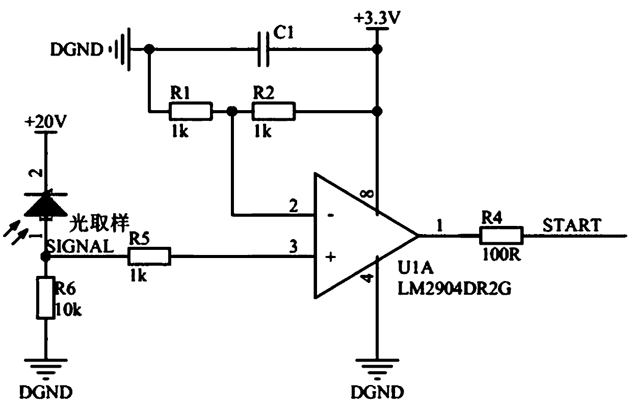
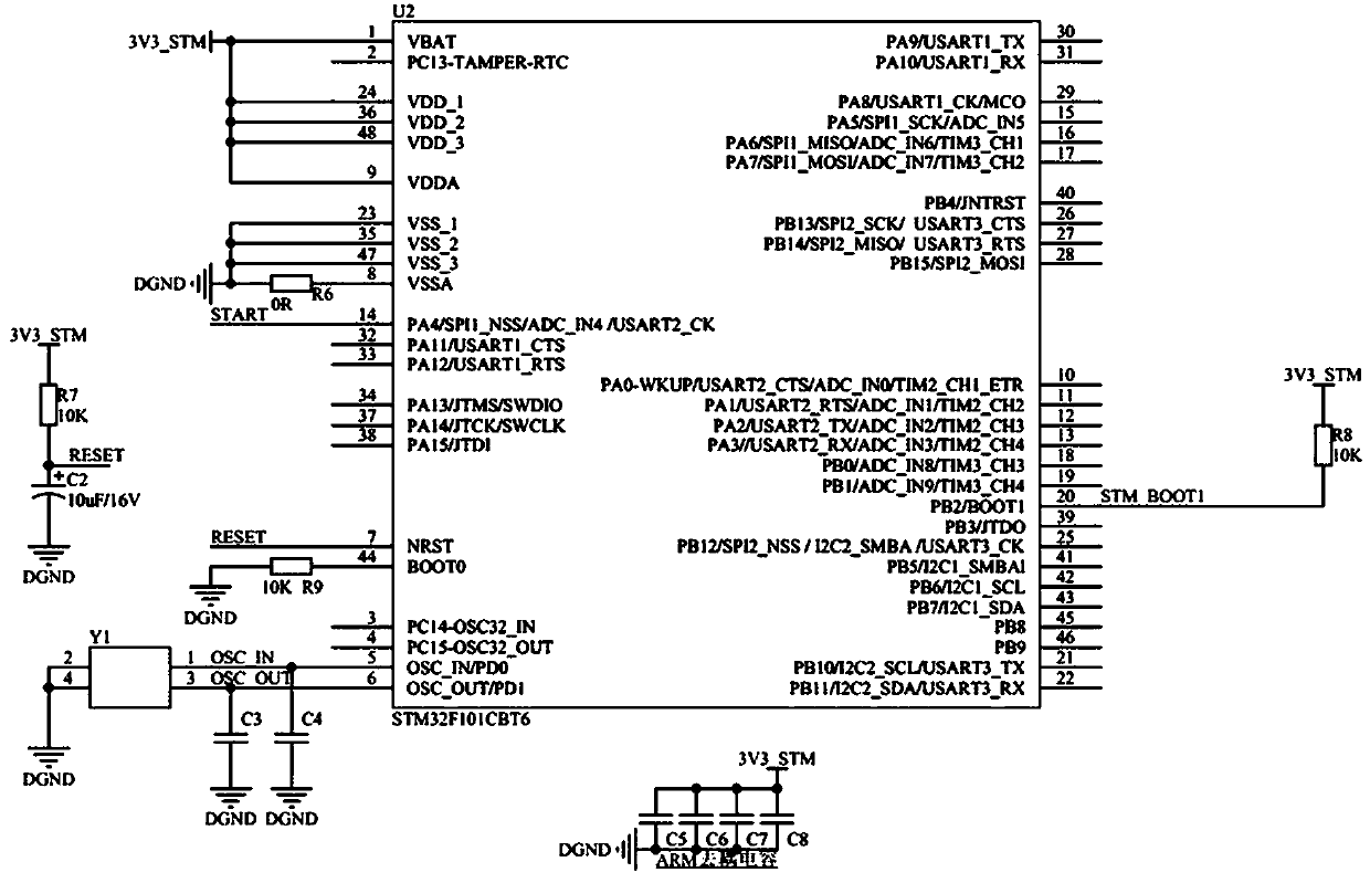
[0019] A light detection circuit suitable for self-inspection of laser range finders, such as figure 1 As shown, it includes an MCU minimum system and an MCU control circuit, and also includes an optical signal detection circuit, and the optical signal detection circuit, the MCU minimum system, and the MCU control circuit are connected in sequence, wherein the optical...


PUM


Abstract

The invention provides a light emitting detection circuit suitable for self-inspection of a laser range finder. The circuit comprises an MCU minimum system and an MCU control circuit. The circuit further comprises an optical signal detection circuit. The optical signal detection circuit, the MCU minimum system and the MCU control circuit are connected in sequence. The optical signal detection circuit is used for detecting a transmitting module of the laser range finder in real time, a corresponding digital signal is generated along with the light emitted by the emitting module and is fed backto the MCU minimum system. After receiving the digital signal, the MCU minimum system drives the timer to start timing through the MCU control circuit. The circuit is simple in structure, reasonable in design, compact in logic, efficient and rapid in response and high in adaptive capacity due to mutual cooperation of all modules and circuits, so that the precision of pulse type laser ranging can be improved, and the problem that the ranging precision is low due to the fact that optical signals are not detected in time is solved.

Description

technical field [0001] The invention belongs to the field of laser optoelectronic technology, and in particular relates to a light output detection circuit suitable for self-inspection of a laser distance measuring machine. Background technique [0002] Laser ranging methods are divided into pulse laser ranging and phase laser ranging. Pulse laser ranging has the advantages of long test distance and simple signal processing. The working principle of the traditional pulsed laser ranging is: the laser emits an optical signal to the target to be measured, and then receives the optical signal reflected by the target, and calculates the distance of the target by measuring the round-trip time of the optical signal. [0003] The pulsed laser ranging mainly includes a laser transmitting module, a laser receiving module, a counting module and a power supply module. The laser emitting module emits laser light and starts counting, and stops counting when receiving the echo. At this ti...

Claims


Application Information

Patent Timeline
Patent Type & Authority Applications(China)
IPC IPC(8): G01S17/10G01S7/483G01S7/497
CPCG01S7/483G01S7/497G01S17/10
Inventor 董涛罗潇周巍张国雷郭凯凯王明义裴淑曼张凯祥崔息戈
Owner 洛阳顶扬光电技术有限公司
Why Eureka
Try Eureka