Display device
A technology for display devices and display screens, applied in radiation control devices, instruments, electrical digital data processing, etc., can solve problems such as inconvenient operation, and achieve the effect of convenient and fast remote operation
- Summary
- Abstract
- Description
- Claims
- Application Information
AI Technical Summary
Problems solved by technology
Method used
Image
Examples
Embodiment 1
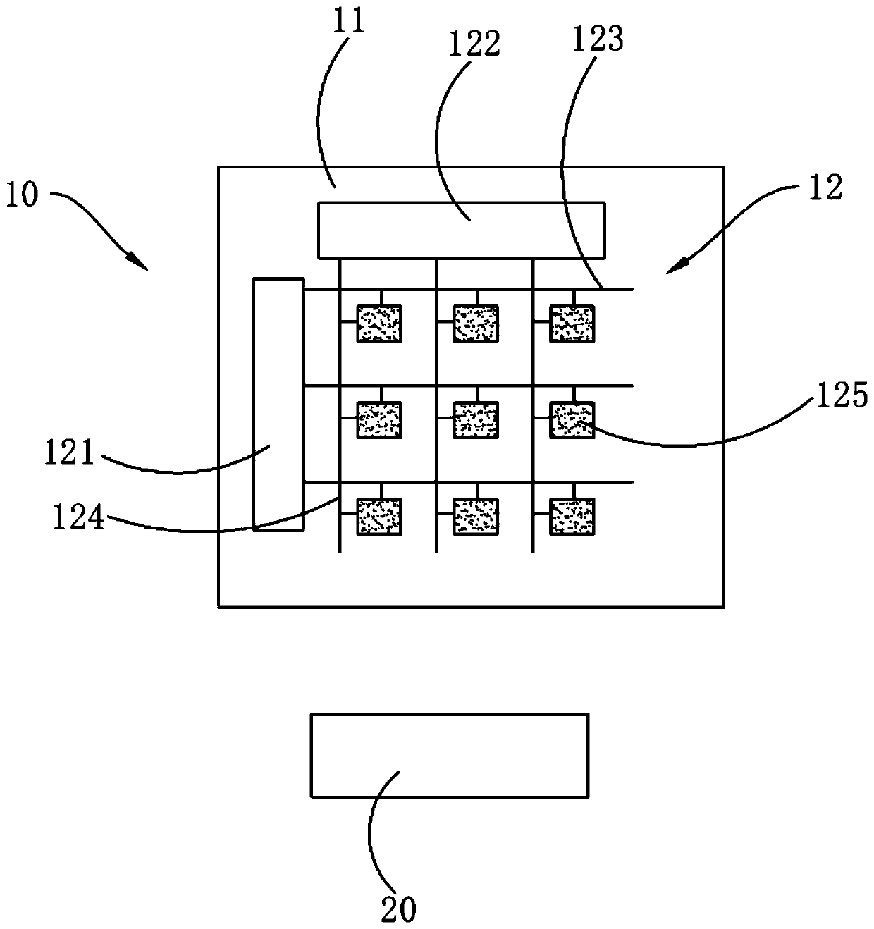
[0062] A display device such as figure 1 As shown, the display device includes a beam emitter 20 and a display panel 10 .
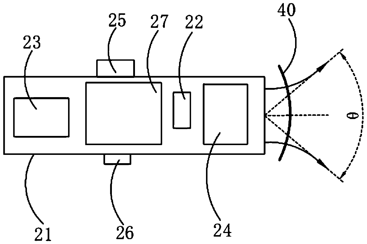
[0063] Specifically, the beam emitter 20 emits a first beam used to mark the input position on the display panel 10 , and operates on the input position marked by the first beam.
[0064] It should be noted that, the first light beam is a positioning light beam, which is used to locate the point on the display panel 10 that requires optical control manipulation, that is, to mark the input position on the display panel 10, and the first The light beam is visible light, so that human eyes can see the projected position of the first light beam on the display panel 10 .
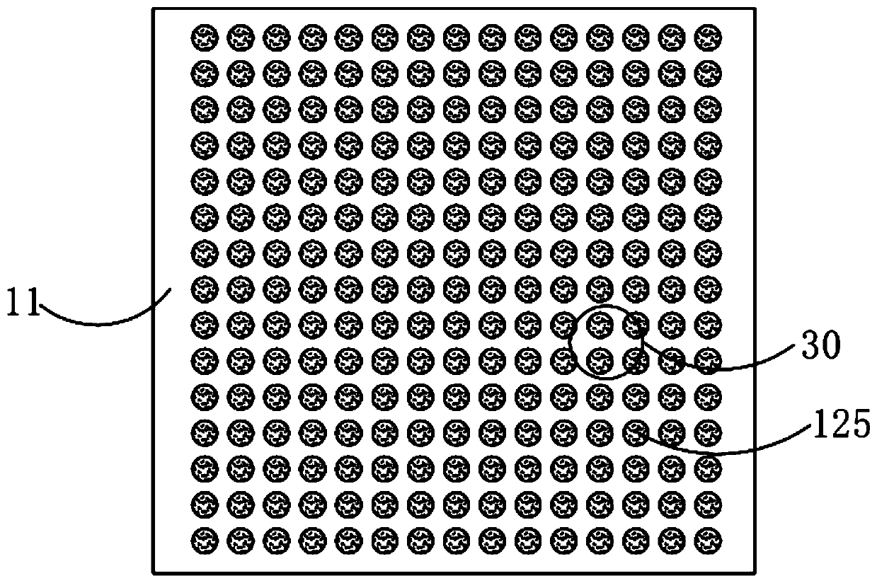
[0065] Specifically, the display panel 10 includes a display screen body 11 and an optical control layer 12 disposed on the light-emitting side of the display screen body 11. The photosensitive device 125 of the first light beam on the light beam, and the photosensitive device 125 outputs ...
Embodiment 2
[0113] A display device such as Image 6 As shown, the difference from Embodiment 1 is that the display panel 10 further includes a touch device 13 disposed on the light-emitting side of the display body 11, and the touch device 13 includes spaced apart emitter electrodes. 131 and the receiving electrode 132 , a touch capacitance is formed between the transmitting electrode 131 and the receiving electrode 132 .
[0114] It should be noted that a touch capacitance is formed between the transmitting electrode 131 and the receiving electrode 132 , and the touch capacitance is a mutual capacitance. When a finger touches the display panel 10, the touch capacitance changes, and the touch device 13 sends a touch signal to the drive module of the display panel 10, and the drive module determines the touch position according to the touch signal and performs the touch control on the touch position. Corresponding operations enable the display panel 10 to have light control functions and...
Embodiment 3
[0127] A display device such as Figure 12 As shown, the difference from Embodiment 2 is that the transmitting electrode 131 and the receiving electrode 132 are arranged on the same layer, and the side of the first passivation layer 128 away from the display body 11 is provided with a flat layer. 17, the transmitting electrode 131 and the receiving electrode 132 are disposed on the planar layer 17, and a second passivation layer 18 covering the transmitting electrode 131 and the receiving electrode 132 is also disposed on the planar layer 17 .
[0128] It should be noted that, by integrating the touch device 13 on the top of the light control layer 12, it is possible to prevent the arrangement of the touch device 13 and the light control device from interfering with each other and cause the display panel 10 to be defective, and it is also convenient to improve the touch control of the display panel 10. Sensitivity, at the same time, the transmitting electrode 131 and the rece...
PUM
| Property | Measurement | Unit |
|---|---|---|
| Diameter | aaaaa | aaaaa |
Abstract
Description
Claims
Application Information
 - R&D
- Intellectual Property
- Life Sciences
- Materials
- Tech Scout
- Unparalleled Data Quality
- Higher Quality Content
- 60% Fewer Hallucinations
Browse by: Latest US Patents, China's latest patents, Technical Efficacy Thesaurus, Application Domain, Technology Topic, Popular Technical Reports.
© 2025 PatSnap. All rights reserved.Legal|Privacy policy|Modern Slavery Act Transparency Statement|Sitemap|About US| Contact US: help@patsnap.com


