a display device

A technology of display device and display screen, applied in radiation control devices, instruments, semiconductor devices, etc., can solve problems such as inconvenient operation, and achieve the effect of convenient and fast long-distance operation

Active Publication Date: 2021-10-08
SHENZHEN CHINA STAR OPTOELECTRONICS SEMICON DISPLAY TECH CO LTD
View PDF6 Cites 0 Cited by
  • Summary
  • Abstract
  • Description
  • Claims
  • Application Information

AI Technical Summary

Problems solved by technology

[0004] The embodiment of the present application provides a display device to solve the technical problem of inconvenient operation when the user uses the display panel as a TV display device at a distance in the existing display device

Method used


Image

  • a display device
  • a display device
  • a display device

Examples


Embodiment 1

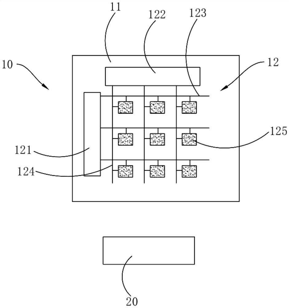
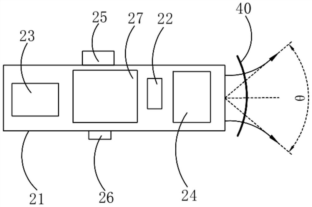
[0062] A display device such as figure 1 As shown, the display device includes a beam emitter 20 and a display panel 10 .

[0063] Specifically, the beam emitter 20 emits a first beam used to mark the input position on the display panel 10 , and operates on the input position marked by the first beam.

[0064] It should be noted that, the first light beam is a positioning light beam, which is used to locate the point on the display panel 10 that requires optical control manipulation, that is, to mark the input position on the display panel 10, and the first The light beam is visible light, so that human eyes can see the projected position of the first light beam on the display panel 10 .

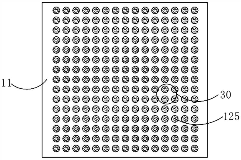
[0065] Specifically, the display panel 10 includes a display screen body 11 and an optical control layer 12 disposed on the light-emitting side of the display screen body 11. The photosensitive device 125 of the first light beam on the light beam, and the photosensitive device 125 outputs ...

Embodiment 2

[0113] A display device such as Figure 6 As shown, the difference from Embodiment 1 is that the display panel 10 further includes a touch device 13 disposed on the light-emitting side of the display body 11, and the touch device 13 includes spaced apart emitter electrodes. 131 and the receiving electrode 132 , a touch capacitance is formed between the transmitting electrode 131 and the receiving electrode 132 .

[0114] It should be noted that a touch capacitance is formed between the transmitting electrode 131 and the receiving electrode 132 , and the touch capacitance is a mutual capacitance. When a finger touches the display panel 10, the touch capacitance changes, and the touch device 13 sends a touch signal to the drive module of the display panel 10, and the drive module determines the touch position according to the touch signal and performs the touch control on the touch position. Corresponding operations enable the display panel 10 to have light control functions an...

Embodiment 3

[0127] A display device such as Figure 12 As shown, the difference from Embodiment 2 is that the transmitting electrode 131 and the receiving electrode 132 are arranged on the same layer, and the side of the first passivation layer 128 away from the display body 11 is provided with a flat layer. 17, the transmitting electrode 131 and the receiving electrode 132 are disposed on the planar layer 17, and a second passivation layer 18 covering the transmitting electrode 131 and the receiving electrode 132 is also disposed on the planar layer 17 .

[0128] It should be noted that, by integrating the touch device 13 on the top of the light control layer 12, it is possible to prevent the arrangement of the touch device 13 and the light control device from interfering with each other and cause the display panel 10 to be defective, and it is also convenient to improve the touch control of the display panel 10. Sensitivity, at the same time, the transmitting electrode 131 and the rece...


PUM

PropertyMeasurementUnit
diameteraaaaaaaaaa
strengthaaaaaaaaaa

Abstract

The application discloses a display device, including a beam emitter and a display panel; the beam emitter emits a first beam used to mark an input position on the display panel, and operates on the input position marked by the first beam; the display panel includes The display body and the light control layer, the light control layer includes a photosensitive device, a control module and a reading module; the photosensitive device outputs a photosensitive signal according to the sensing result, and the control module is used to output a control signal for controlling the opening and closing of the photosensitive device, and read The module is used to read the sensing signal output by the photosensitive device, and determine the projected position of the first light beam on the display panel according to the sensed signal, and the reading module is also used to perform corresponding operations on the projected position of the first light beam. When the display panel needs to be operated remotely, the display panel can be operated by using the beam transmitter, and the input position can be quickly realized by moving the beam transmitter, and the remote operation of the display panel is convenient and quick.

Description

technical field [0001] The present application relates to the field of display technology, and in particular to a display device. Background technique [0002] With the development of the times, display panels are also more and more widely used. When the user uses the display panel as a TV display device at a long distance, the display panel is mostly operated by directly touching it or using a remote controller to override it. [0003] When direct touch operation is adopted, the user needs to go to the front of the display panel to perform direct touch operation, which is very inconvenient. However, the remote control of the display panel through the remote control is mainly realized by the buttons of the remote control. When making a selection, it is often necessary to perform multiple operations through the remote controller to move the cursor to the corresponding icon, and the operation is also very inconvenient. Contents of the invention [0004] An embodiment of th...

Claims


Application Information

Patent Timeline
Patent Type & Authority Patents(China)
IPC IPC(8): H01L27/144G06F3/041
CPCH01L27/1443H01L27/1446G06F3/0412G06F3/0421G06F3/0446G06F3/03542G06F3/0386G06F3/042
Inventor 江淼陈黎暄张鑫温雷查宝
Owner SHENZHEN CHINA STAR OPTOELECTRONICS SEMICON DISPLAY TECH CO LTD
Why Eureka
Try Eureka