Control method of electric tool

A control method and technology of electric tools, applied in the direction of electrical components, circuit devices, emergency protection circuit devices, etc., can solve problems such as high cost, troublesome manufacturing, and complex structure of mechanical clutches

Inactive Publication Date: 2020-08-11
陈永福
View PDF0 Cites 1 Cited by
  • Summary
  • Abstract
  • Description
  • Claims
  • Application Information

AI Technical Summary

Problems solved by technology

However, the structure of the above-mentioned mechanical clutches is relatively complicated, the manufacture is troublesome, and the cost is relatively high.

Method used


Image

  • Control method of electric tool
  • Control method of electric tool
  • Control method of electric tool

Examples


Embodiment

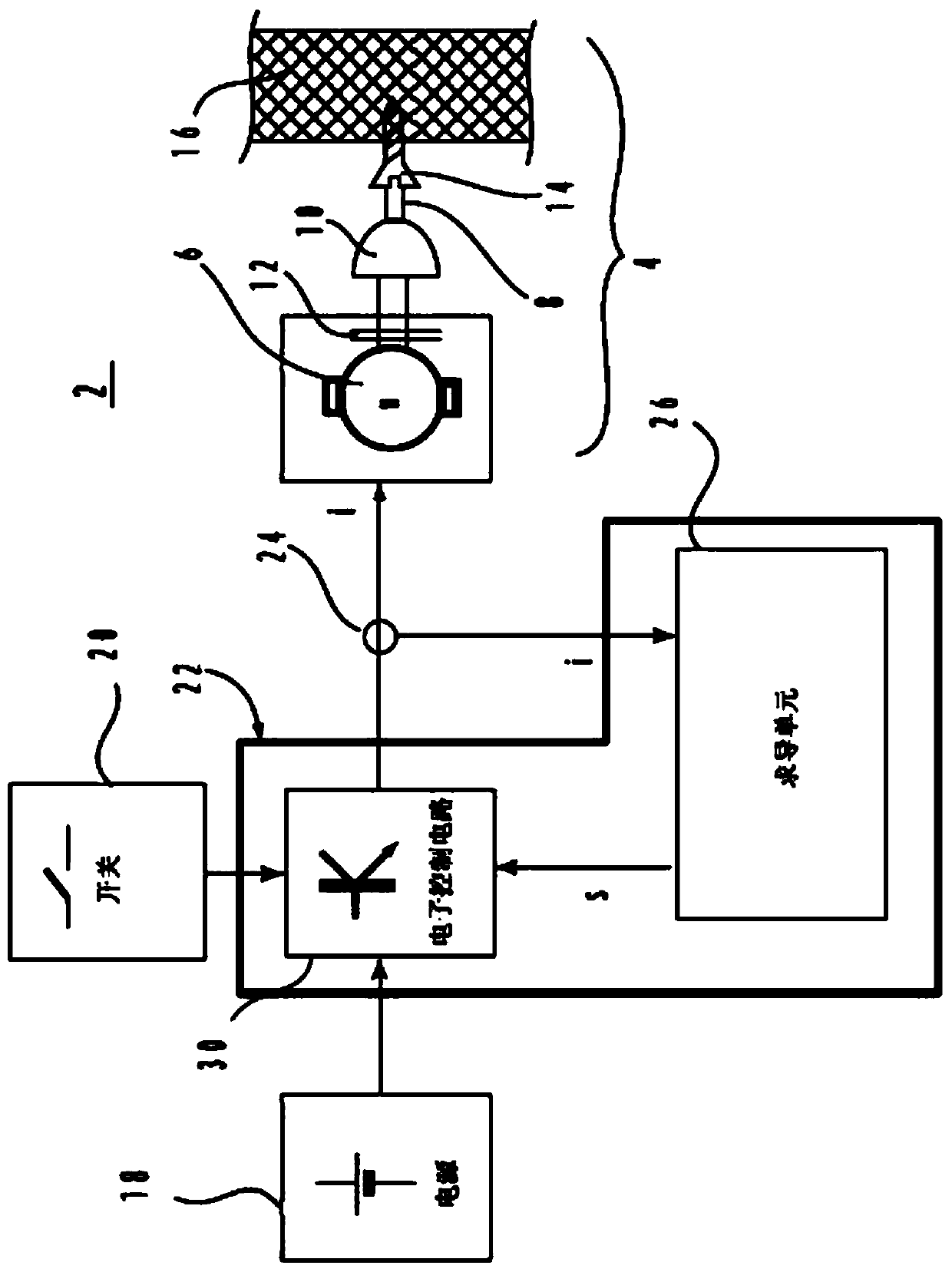
[0025] An embodiment of the present invention provides a control method of an electric tool, such as Figure 6 As shown, the method includes the following steps:

[0026] S1, measuring the parameters used to represent the load of the output shaft that change with time, the parameters include a variety of parameters, such as current, voltage, speed, etc. The measurement method may be sampling at a fixed period.

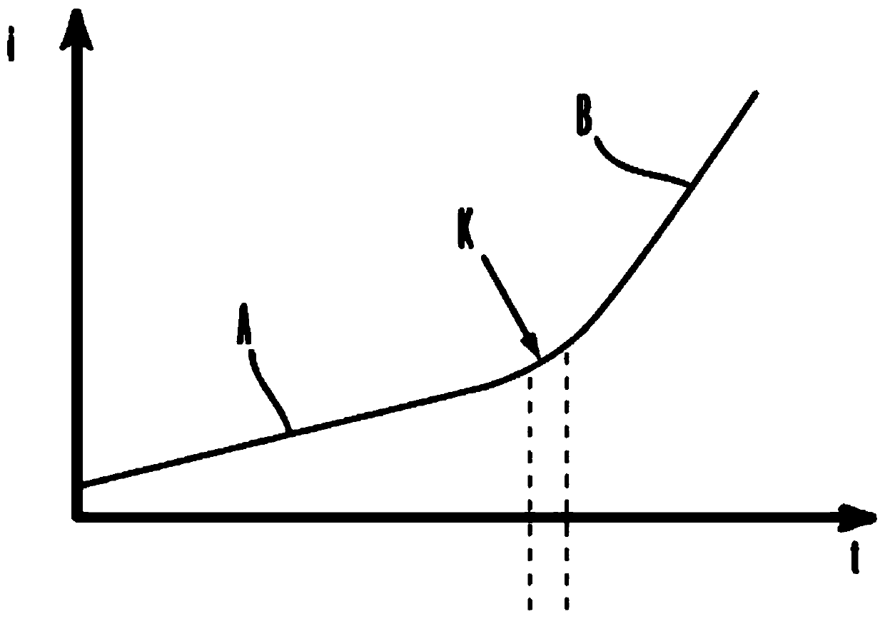
[0027] S2, obtain the derivative of the parameter with respect to time, this derivative is actually figure 1 The slope of the middle curve. There are many ways to calculate the derivative, which will be described in detail below.

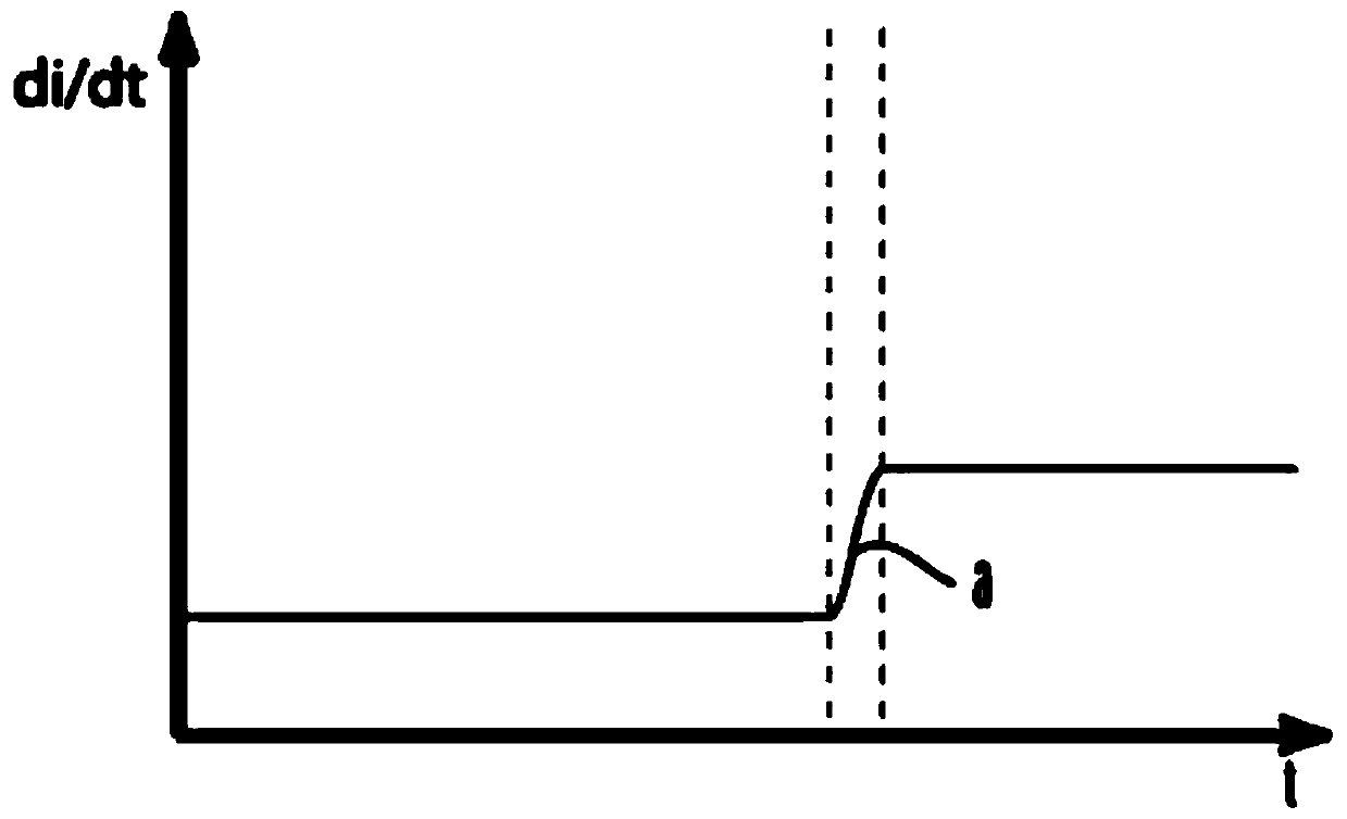
[0028] S3, judging whether the obtained derivative is greater than a derivative threshold, the derivative threshold may be a predetermined and stored value, and the derivative threshold may be one or more. When the obtained derivative is greater than the derivative threshold, step S4 is executed; otherwise, the derivative is continuously...


PUM


Abstract

The invention relates to a control method of an electric tool. The electric tool comprises a motor and an output shaft rotationally driven by the motor, wherein the output shaft is used for outputtingrotating torque to drive a working head to work on a workpiece. The control method comprises the following steps of measuring a parameter which is changed along with time and is used for representinga load of the output shaft; obtaining a derivative of the parameter to the time; judging whether the derivative is greater than a derivative threshold value or not; when the derivative is greater than the derivative threshold, calculating an intercept according to the parameter value and the time value, and calculating a parameter threshold according to the intercept, the derivative threshold andthe time value; generating a control signal when a trigger condition is satisfied between the measured parameter value and the parameter threshold. The control method is advantaged in that the torqueoutput of the electric tool is interrupted according to the control signal, that a workpiece driven by a working head of the electric tool reaches a preset position is automatically ensured, and theworkpiece cannot further cross the preset position.

Description

technical field [0001] The invention relates to the field of electric tool products, in particular to a control method of the electric tool. Background technique [0002] Different types of screws have different body diameters, or different head shapes, so that they drill into the same board differently. In addition, different wood boards have different hardness due to different materials, so the situation of the same screw drilling into wood boards of different materials is not the same. Usually, during the use of an electric screwdriver, the user needs to drill the screw until the head is close to the surface of the workpiece. In this way, the user needs to pay attention to the drilling process very carefully to control the motor to stop when the head of the screw is close to the surface of the workpiece. change. Thereby, on the one hand, the screw head is prevented from being drilled into the plank too deeply, and on the other hand, the motor is overloaded due to excess...

Claims


Application Information

Patent Timeline
Patent Type & Authority Applications(China)
IPC IPC(8): H02H7/085H02H1/00G01D21/02
CPCG01D21/02H02H1/0007H02H7/085
Inventor 陈永福
Owner 陈永福
Why Eureka
Try Eureka