
A hanging fire extinguishing device applied to drones

A technology of fire extinguishing device and unmanned aerial vehicle, which is applied in fire rescue and other directions, can solve the problems of delayed fire fighting time, crash, time-consuming and other problems, and achieve the effect of prolonging the rescue time, stabilizing the unmanned aerial vehicle, and saving time

Active Publication Date: 2021-06-11
CIVIL AVIATION FLIGHT UNIV OF CHINA
View PDF14 Cites 0 Cited by
  • Summary
  • Abstract
  • Description
  • Claims
  • Application Information

AI Technical Summary

Problems solved by technology

[0006] 1. Since the fire-fighting drone carries a fire-extinguishing device, its own weight increases, and the displacement of the drone needs to consume more power. When the fire-fighting drone is connected to a high-pressure water gun for fire extinguishing, it is necessary to realize spraying while extinguishing the fire. Displacement, relying solely on the rotor is very difficult. Displacement when spraying water will make the flight state of the multi-rotor UAV extremely unstable, wobbling and shaking, and in serious cases, there is a danger of crashing. The current displacement process, It is often to stop spraying water, and then spray water after adjusting the position, which not only takes a long time, but also delays the fire fighting time, the efficiency is not high, and the practicability is not strong;
[0007] 2. Existing UAVs are used for fire extinguishing, usually using multi-rotor UAVs, which do not require take-off and landing sites in cities, and are relatively flexible to use. However, when this UAV is disturbed by external forces, its own flight is stable In application, the high-pressure water gun is often connected with the shell of the fire-fighting drone. When the high-pressure water gun sprays, the jet recoil is relatively large, which is difficult to overcome only by the aircraft itself.

Method used


Image

  • A hanging fire extinguishing device applied to drones
  • A hanging fire extinguishing device applied to drones
  • A hanging fire extinguishing device applied to drones

Examples


Embodiment 1

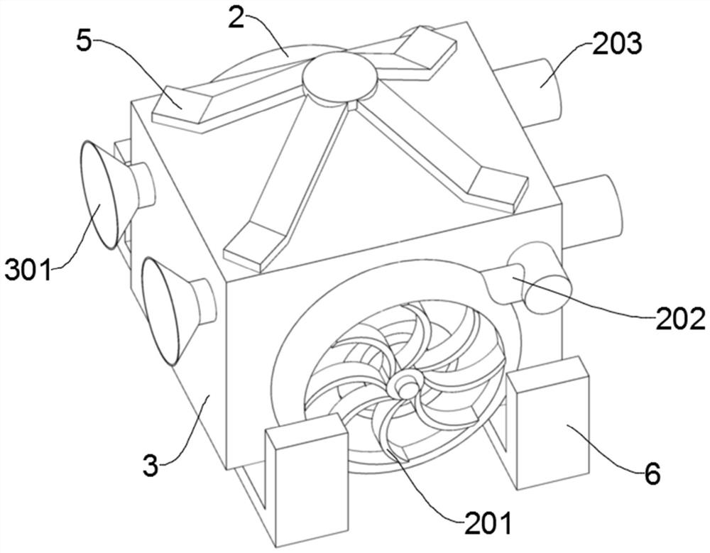
[0045] This embodiment is a structure of a suspended fire extinguishing device applied to an unmanned aerial vehicle, as shown in Figures 1 to 5, including an installation box 3, a hydraulic component, a wind component, and a control system, and the installation box 3 is provided with a Space, the hydraulic components and the wind components are symmetrically arranged on both sides of the installation box 3, that is, the hydraulic components are arranged on the inner wall of the installation box 3, and the wind components are arranged on the outer wall of the installation box 3 , the hydraulic component and the wind component are linked through the transmission shaft 4, and the control system is used to control the speed of the hydraulic component;

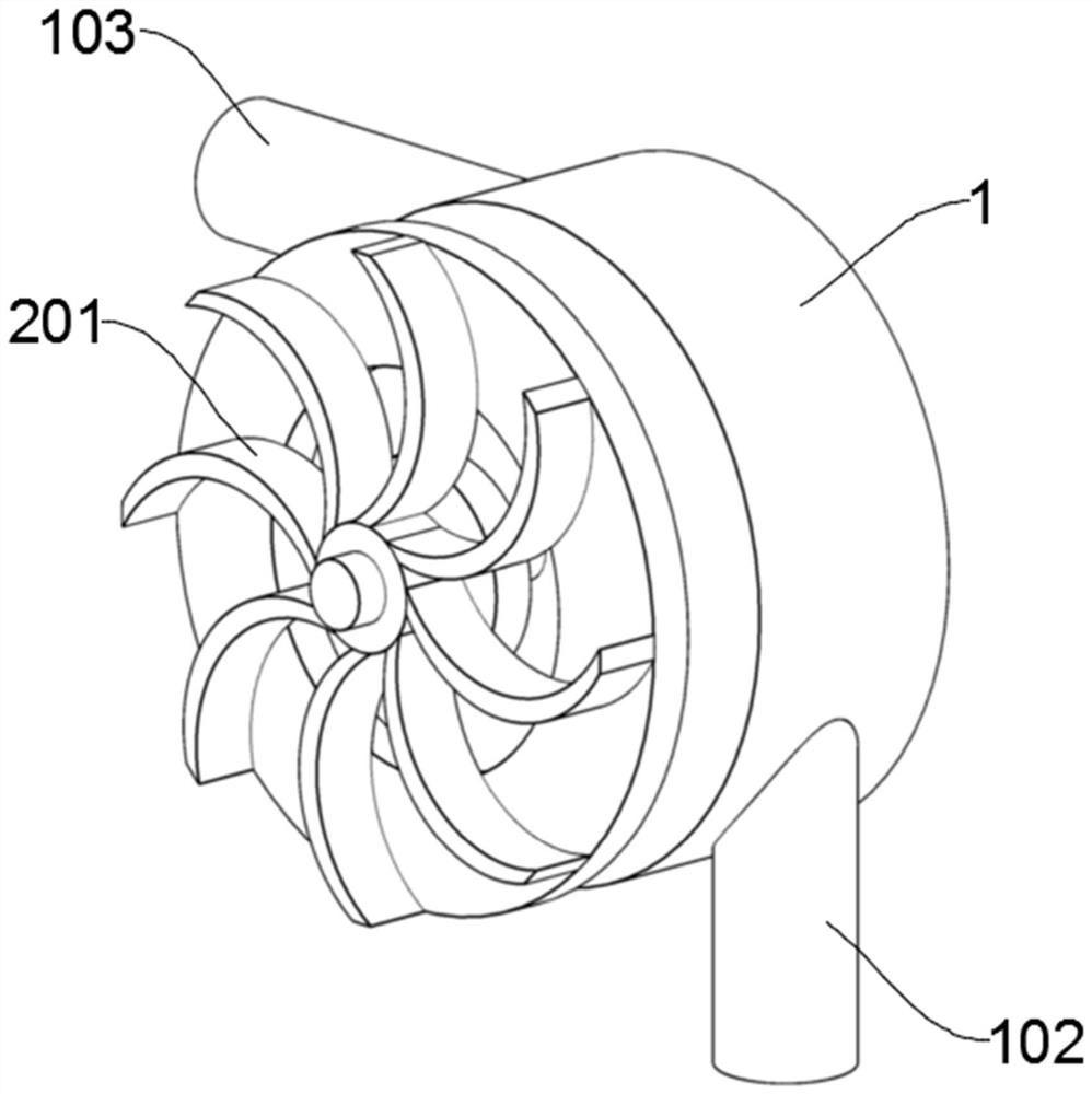
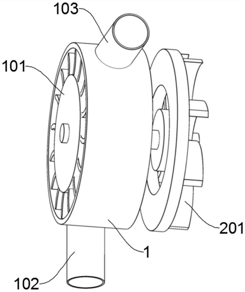
[0046] The hydraulic assembly includes a first housing 1, a water turbine 101, an inlet pipe 102, and an outlet pipe 103. The first housing 1 is a hollow cylinder, and the first housing 1 wraps the water turbine 101, and The first...


PUM


Abstract

The invention discloses a suspended fire extinguishing device applied to unmanned aerial vehicles, which includes an installation box, a hydraulic component, a wind component, and a control system. The installation box is provided with an accommodation space, and the hydraulic component and the wind component are arranged symmetrically. On both sides of the installation box, the hydraulic component and the wind component are linked through the transmission shaft, and the control system is used to control the speed of the hydraulic component; the hydraulic turbine and the fan impeller are used to offset the The recoil force generated by part of the high-pressure water gun spraying water ensures the flight stability of the multi-rotor UAV during the spraying process. When the multi-rotor drone is displaced, the pressure difference generated by the rotation of the fan impeller plays the role of assisting the displacement of the multi-rotor drone, saving the time for adjusting the spray angle of the multi-rotor unmanned, improving the efficiency of fire extinguishing, and prolonging the life of the multi-rotor drone. Rescue time, more practical.

Description

technical field [0001] The invention relates to the technical field of fire fighting equipment, in particular to a hanging fire extinguishing device applied to a drone. Background technique [0002] With the popularization of science and technology, unmanned aerial vehicles have gradually entered everyone's field of vision. Among them, industrial-grade unmanned aerial vehicles have gradually been applied to various fields to play their own role, especially in high-risk areas focusing on firefighting. UAVs are used to replace some The importance of human action to the fire protection industry is self-evident; [0003] With the development of urbanization, there are more and more high-rise and super high-rise buildings. Once a fire occurs, the reaction speed and fire fighting are extremely difficult, especially for buildings above 30m, which basically rely on the fire-fighting devices inside the building. Fire-fighting devices have limited effects, and in many cases, the inte...

Claims


Application Information

Patent Timeline
Patent Type & Authority Patents(China)
IPC IPC(8): A62C3/02A62C31/03A62C31/28A62C37/40
CPCA62C3/0242A62C31/03A62C31/28A62C37/40
Inventor 王明武李建伟孟亚伟陶波
Owner CIVIL AVIATION FLIGHT UNIV OF CHINA
Learn More