Catalytic combustion waste gas treatment device with baffle plate structure and method

A waste gas treatment device and catalytic combustion technology, applied in the direction of combustion methods, chemical instruments and methods, combustion types, etc., can solve problems such as baffle blockage, inconvenient removal of baffle plates, and easy accumulation of impurities, etc., to reduce work difficulty , easy to clean, and ensure the effect of efficiency

Inactive Publication Date: 2020-08-14
唐胜华
View PDF6 Cites 1 Cited by
  • Summary
  • Abstract
  • Description
  • Claims
  • Application Information

AI Technical Summary

Problems solved by technology

[0002] With the increasing emphasis on environmental protection, the quality requirements for exhaust gas emissions are gradually increasing. When using catalytic combustion treatment equipment to treat exhaust gas, it is necessary to use a baffle structure to change the flow direction of the gas. The baffle is used for a long time. During the process, a large amount of impurities tend to accumulate on the surface, causing the baffle to be easily blocked, and regular cleaning is required. However, the baffle is generally installed inside the pipe, and the pipe is a whole, and both ends are fixedly connected. As a result, it is inconvenient to take out the baffles. Therefore, we propose a catalytic combustion exhaust gas treatment device and method with a baffle structure.

Method used


Image

  • Catalytic combustion waste gas treatment device with baffle plate structure and method
  • Catalytic combustion waste gas treatment device with baffle plate structure and method
  • Catalytic combustion waste gas treatment device with baffle plate structure and method

Examples


Embodiment Construction

[0025] The following will clearly and completely describe the technical solutions in the embodiments of the present invention with reference to the accompanying drawings in the embodiments of the present invention. Obviously, the described embodiments are only some, not all, embodiments of the present invention. Based on the embodiments of the present invention, all other embodiments obtained by persons of ordinary skill in the art without making creative efforts belong to the protection scope of the present invention.

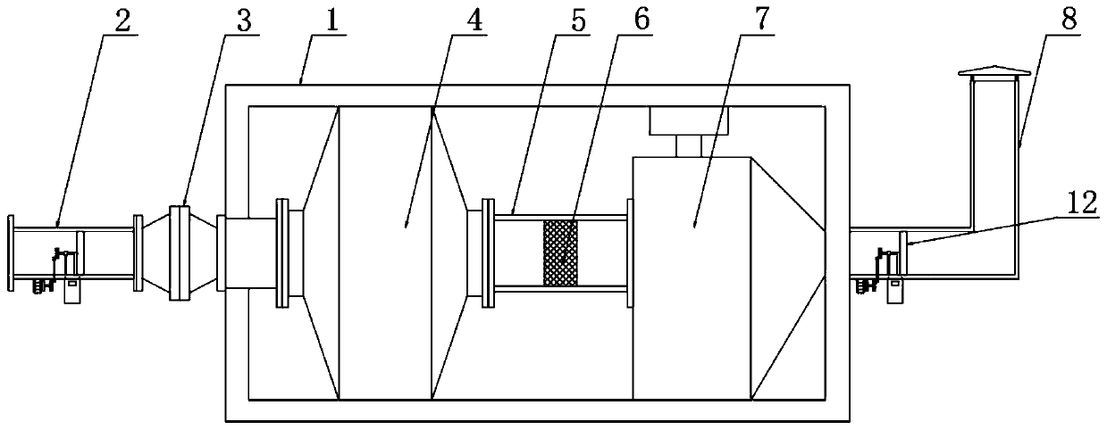
[0026] The invention provides a technical solution: a catalytic combustion exhaust gas treatment device with a baffle structure, please refer to figure 1 , including the waste gas treatment equipment body 1;

[0027] see figure 1 , the left outer wall of the exhaust gas treatment equipment body 1 is fixedly connected with the flame arrester 3, the left outer wall of the flame arrester 3 is fixedly connected with the intake pipe 2, and the left side of the inn...


PUM


Abstract

The invention discloses a catalytic combustion waste gas treatment device with a baffle plate structure, and belongs to the technical field of waste gas treatment equipment. The device comprises a waste gas treatment equipment body, a heat exchanger is arranged on the left side of the inner cavity of the waste gas treatment equipment body; the right outer wall of the heat exchanger is fixedly connected with a pipeline; a baffle plate is arranged in the inner cavity of the pipeline; the right end of the pipeline is communicated with a catalytic bed; an opening is formed in the outer wall of thefront side of the pipe body; a moving plate is hinged to the bottom inner wall of the front side of the opening; the outer wall of the top of the moving plate is fixedly connected with a telescopic device; the outer wall of the top of the pipe body is fixedly connected with a supporting rod. The outer wall of the front side of the supporting rod is fixedly connected with a lantern ring, the lantern ring is arranged on the outer wall of the telescopic device in a sleeving mode, a pull rod is moved downwards in the device, a moving rod is moved out of the inner cavity of the lantern ring, a moving plate is disconnected with the pipe body, and the front side wall of the pipeline is opened so that the baffle plate is conveniently taken out and cleaned, overhauled or replaced.

Description

technical field [0001] The invention relates to the technical field of exhaust gas treatment equipment, in particular to a catalytic combustion exhaust gas treatment device and method with a baffle structure. Background technique [0002] With the increasing emphasis on environmental protection, the quality requirements for exhaust gas emissions are gradually increasing. When using catalytic combustion treatment equipment to treat exhaust gas, it is necessary to use a baffle structure to change the flow direction of the gas. The baffle is used for a long time. During the process, a large amount of impurities tend to accumulate on the surface, causing the baffle to be easily blocked, and regular cleaning is required. However, the baffle is generally installed inside the pipe, and the pipe is a whole, and both ends are fixedly connected. As a result, it is inconvenient to take out the baffles. Therefore, we propose a catalytic combustion exhaust gas treatment device and method...

Claims


Application Information

Patent Timeline
Patent Type & Authority Applications(China)
IPC IPC(8): B01D46/10B01D46/00F23G7/07
CPCB01D46/10F23G7/07B01D46/681
Inventor 唐胜华
Owner 唐胜华
Why Eureka
Try Eureka