Metal plate bending machining die

A technology for processing metal sheets and molds, which is applied in the field of sheet metal processing, can solve the problems of reducing bending forming accuracy, deviation between main bending point and bending structure, and asymmetry of bending formed parts, so as to improve bending quality and accuracy , Precise control of the movement distance, and the effect of improving the scope of application

Active Publication Date: 2020-08-14
ANHUI DONGHAI MACHINE MFG CO LTD
View PDF5 Cites 1 Cited by
  • Summary
  • Abstract
  • Description
  • Claims
  • Application Information

AI Technical Summary

Problems solved by technology

[0003] 1. The common sheet metal bending device is only for the processing of a single type of formed parts, and the width and bending angle of the formed parts are fixed, so the device as a whole cannot be fully utilized. At the same time, when placing the metal sheet manually, it is easy to cause There is a deviation between the main bending point and the bending structure, so that the bent formed part is asymmetrical or irregular;
[0004] 2. The multi-directional freedom of the metal sheet cannot be effectively limited and fixed, so the metal sheet is prone to offset during the bending process, which in turn increases the production rate of defective formed parts and reduces the bending accuracy At the same time, the degree of fit between the main bending position on the metal sheet and the bending die is low, so that the bending degree of the two ends of the metal sheet is inconsistent

Method used


Image

  • Metal plate bending machining die
  • Metal plate bending machining die
  • Metal plate bending machining die

Examples


Embodiment Construction

[0031] The embodiments of the present invention will be described in detail below with reference to the accompanying drawings, but the present invention can be implemented in many different ways as defined and covered by the claims.

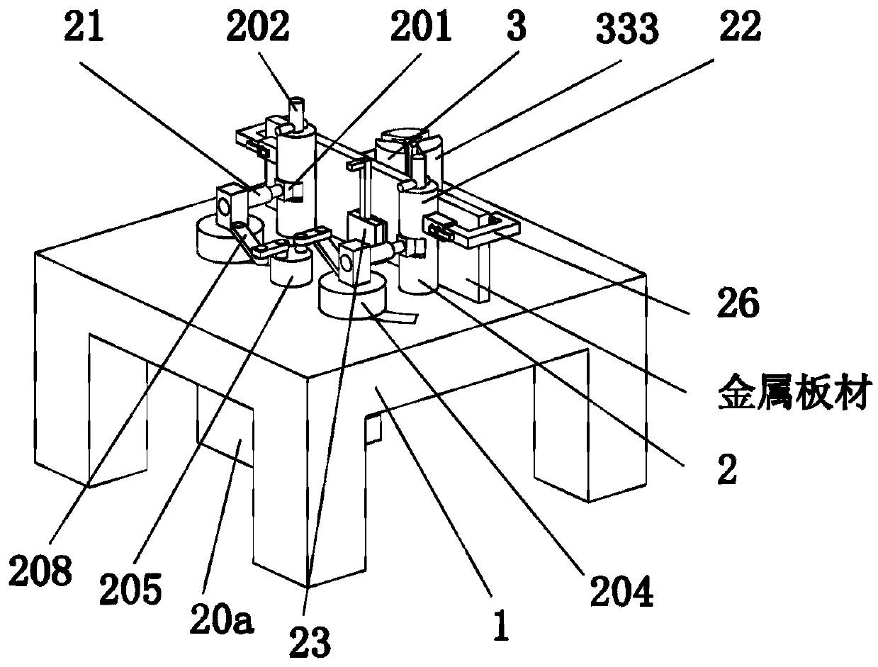
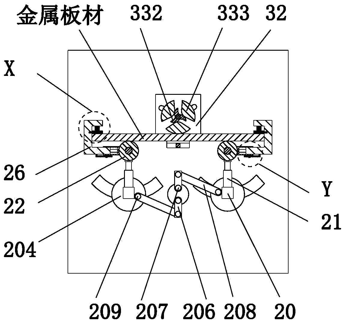
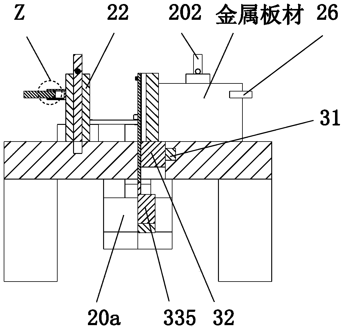
[0032] Such as Figure 1 to Figure 9 As shown, a sheet metal bending processing mold includes a workbench 1, a clamping mechanism 2 and an inner bending unit 3. The front end of the upper end of the workbench 1 is symmetrically provided with a clamping mechanism 2. The rear end is installed with an inward bending unit 3 in a sliding fit manner, and the inward bending unit 3 is located at the rear middle side of the clamping and bending mechanism 2 .

[0033] The clamping mechanism 2 includes a vertical block 20, an electric push rod 21, an outer folding roller 22, a counter plate 23, a hollow rod 24, a No. 1 electric slider 25, a U-shaped card frame 26, a compression spring 27 and a pressing block 28 The vertical block 20 is arranged symmetrical...


PUM


Abstract

The invention relates to a metal plate bending machining die. The metal plate bending machining die comprises a workbench, a clamping and bending mechanisms and an inward bending unit, wherein the clamping and bending mechanism is arranged at the front end of the upper end of the workbench in a left and right symmetry mode, the inward bending unit is installed at the rear end of the upper end of the workbench in a sliding fit mode, and the inward bending unit is located on the rear middle side of the clamping and bending mechanism. According to the metal plate bending machining die, the designconcept of a multi-aspect adjustable structure is adopted for metal plate bending machining, and on the basis of longitudinal bending, a structure with the function of controlling the bending angle and the width of a formed part is additionally arranged on the whole device, so that the application range of the whole device is greatly widened; and meanwhile, a plurality of structures with limitingand guiding functions are adopted to improve the bending quality and precision of a metal plate.

Description

technical field [0001] The invention relates to the technical field of plate processing, in particular to a metal plate bending processing die. Background technique [0002] Plates are made into flat rectangular building material plates of standard size. They are used in the construction industry as components of walls, ceilings or floors. They also refer to forged, rolled or cast metal plates, which are divided into thin plates and medium plates. , thick plate, extra thick plate, usually made into a flat rectangular building material plate of standard size, among which the common processing methods of metal plate include punching, bending, cutting, etc., the plate product has a flat shape, a large aspect ratio, and a surface area per unit volume It is also very large. This shape feature enhances its ability to contain and cover. It can be cut, bent, stamped, welded, and made into various product components. It can be bent and welded into various complex sections of steel, s...

Claims


Application Information

Patent Timeline
Patent Type & Authority Applications(China)
IPC IPC(8): B21D5/00B21D37/10B21D43/00
CPCB21D5/00B21D5/002B21D5/006B21D37/10
Inventor 王斌斌金严
Owner ANHUI DONGHAI MACHINE MFG CO LTD
Why Eureka
Try Eureka