Steel bar welding device for pipe gallery construction

A welding device and steel bar technology, applied in auxiliary devices, welding equipment, auxiliary welding equipment and other directions, can solve the problems of the movement and shaking of the steel cage, the decrease of the strength of the steel cage, and the change of the structural strength of the steel cage, so as to improve the production efficiency and improve the stability. Sexual, easy-to-use effects

Active Publication Date: 2020-08-14
BEIJING MUNICIPAL ROAD & BRIDGE
View PDF7 Cites 7 Cited by
  • Summary
  • Abstract
  • Description
  • Claims
  • Application Information

AI Technical Summary

Problems solved by technology

[0004] However, the above-mentioned technical solution has the following defects: because the side of the seam welding machine in the discharge direction does not provide a supporting device for the steel cage, and after the seam welder completes the seam welding of the steel bar, the sliding of the traction mechanism will drive the processing Good steel cage discharge, because the steel cage itself is long and heavy, and the steel cage is easy to shake during the moving process
[0005] When the steel cage is welded, there will inevitably be a certain amount of heat to reduce the strength of the steel cage, and with the shaking of the steel cage, it is easy to cause a certain bending of the formed steel cage, resulting in a decrease in the structural strength of the steel cage. The change has affected the production quality of the steel cage

Method used


Image

  • Steel bar welding device for pipe gallery construction
  • Steel bar welding device for pipe gallery construction
  • Steel bar welding device for pipe gallery construction

Examples


Embodiment

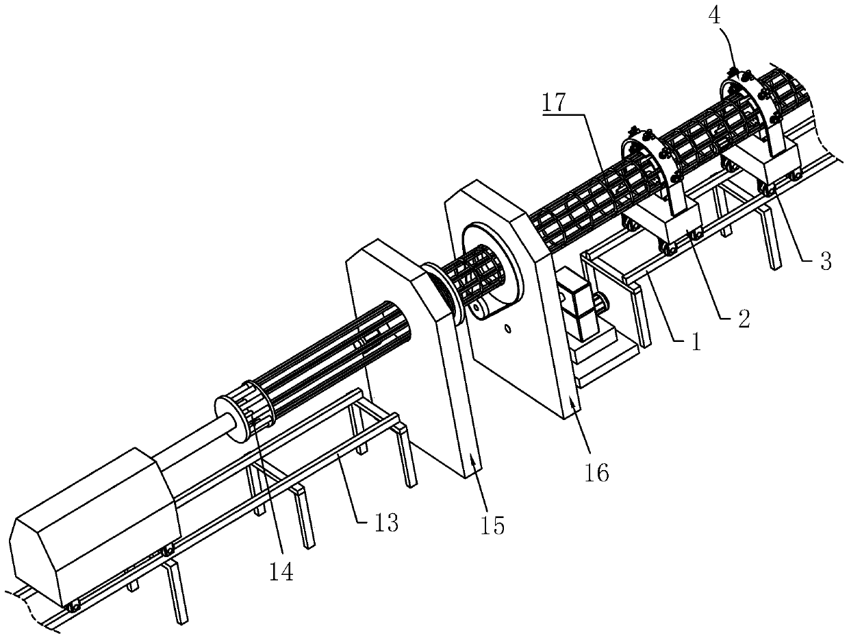
[0042] A steel bar welding device for pipe gallery construction, refer to figure 1 , which includes a track frame 13, a traction mechanism 14 is provided for sliding on the track frame 13, and one side of the traction mechanism 14 is sequentially provided with a winding mechanism 15 and a seam welding mechanism 16; the traction mechanism 14 is used to clamp and drive a plurality of steel bars Move, steel cage 17 utilizes winding mechanism 15 to wind steel wire on a plurality of steel bars during moving, then welds steel bar and steel wire by roll welding mechanism 16, and steel cage 17 can be welded and formed finally.

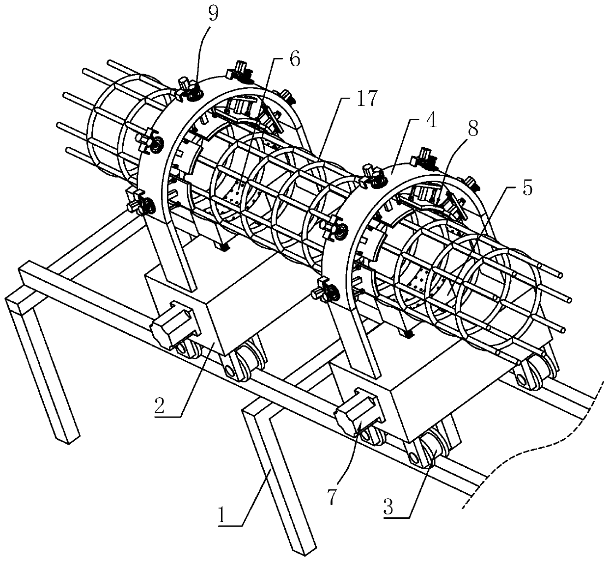
[0043] refer to figure 1 and figure 2 , the roll welding mechanism 16 is provided with a guide rail frame 1 on the side facing away from the winding mechanism 15, the length direction of the guide rail frame 1 is in the same direction as the discharge direction, and a plurality of support seats 2 are provided for the sliding frame between the two guide rail ...


PUM


Abstract

The invention discloses a steel bar welding device for pipe gallery construction, relates to the technical filed of steel bar cage welding, and aims to solve the technical problem that in the prior art, after a steel bar cage is welded and formed by a rolling welder, the steel bar cage is prone to shaking when discharging, resulting in affecting the strength of the steel bar cage. According to thekey points of the technical scheme, the steel bar welding device comprises a guide rail frame located on one side of the discharging direction of a rolling welding mechanism, a plurality of supporting seats slidably erected on the guide rail frame, adjusting frames arranged on the supporting seats, and a rubber seat, an arc-shaped groove for bearing the bottom of the steel bar cage is formed in the upper surface of the rubber seat, lifting assemblies for driving the rubber seat to rise and fall are arranged on the supporting seats, a plurality of elastic compression parts are uniformly arranged on the supporting seats around the circumference of the steel bar cage, and abutting assemblies for driving the elastic compression parts to abut against the outer wall of the steel bar cage are arranged on the adjusting frames. According to the steel bar welding device, the welded steel bar cage is stably supported, the vibration force produced when the steel bar cage is discharged can be effectively reduced, and the stability of the welding process is improved.

Description

technical field [0001] The invention relates to the technical field of reinforcement cage welding, more specifically, it relates to a reinforcement welding device for pipe gallery construction. Background technique [0002] At present, in the process of bridge construction and building construction, it is necessary to prefabricate the reinforcement cage skeleton during the foundation construction process. The reinforcement cage includes a plurality of main reinforcements distributed in a circular array, and stirrups wound spirally on the plurality of main reinforcements. The reinforcement cage is determined by the length of the main reinforcement. The main reinforcement is generally relatively thick. For the convenience of storage and transportation, the main reinforcement is generally about 12 meters long. The production of the reinforcement cage generally requires a reinforcement cage roll welder. [0003] The existing authorization announcement number is that the Chinese ...

Claims


Application Information

Patent Timeline
Patent Type & Authority Applications(China)
IPC IPC(8): B23K37/04B21F27/12
CPCB21F27/121B23K37/0443
Inventor 马瑞李瀛郝钢李昊张文博钟宪磊王成宝王利伟郭侃
Owner BEIJING MUNICIPAL ROAD & BRIDGE
Why Eureka
Try Eureka