Stator section machining clamping device and clamping method

A clamping device and stator segment technology, which is applied to positioning devices, metal processing equipment, metal processing machinery parts, etc., can solve the problems of high risk of turning over the workpiece, affecting the dimensional accuracy and position accuracy of the workpiece, and high processing costs, so as to avoid two The effect of double-turning processing, improving work efficiency and reducing labor intensity

Pending Publication Date: 2020-08-14
JIANGSU ZHENJIANG NEW ENERGY EQUIP
View PDF0 Cites 1 Cited by
  • Summary
  • Abstract
  • Description
  • Claims
  • Application Information

AI Technical Summary

Problems solved by technology

[0002] The stator is an important core component of wind power generation equipment. In the past, most of the wind power field used steel structures or cast iron parts. With the continuous expansion of offshore direct-drive high-power wind turbines, it has now expanded to more than 10MW, and the diameter of the stator frame is getting smaller and smaller. The bigger it is, the integral stator structure is no longer suitable for production, transportation and maintenance. It is necessary to adopt a split structure, and at the same time, it is necessary to control the weight of the parts, that is, the parts are welded into components, tempered and machined. ; and the steel structure is characterized by poor rigidity of the workpiece and relatively large clamping deformation, which brings great difficulties to the entire machining size and precision control, which needs to be grasped and regulated; Processing, so the required processing machine tool specifications are relatively large, the price of the machine tool is expensive, and the processing cost is high; at the same time, when the top of the stator segment is processed, the workpiece needs to be turned over, the risk of turning over the workpiece is high, and the secondary clamping brings a long correction time. Simultaneous correction The error will affect the dimensional accuracy and position accuracy of the workpiece, and the central symmetry of each lobe is difficult to guarantee

Method used


Image

  • Stator section machining clamping device and clamping method
  • Stator section machining clamping device and clamping method
  • Stator section machining clamping device and clamping method

Examples


Embodiment Construction

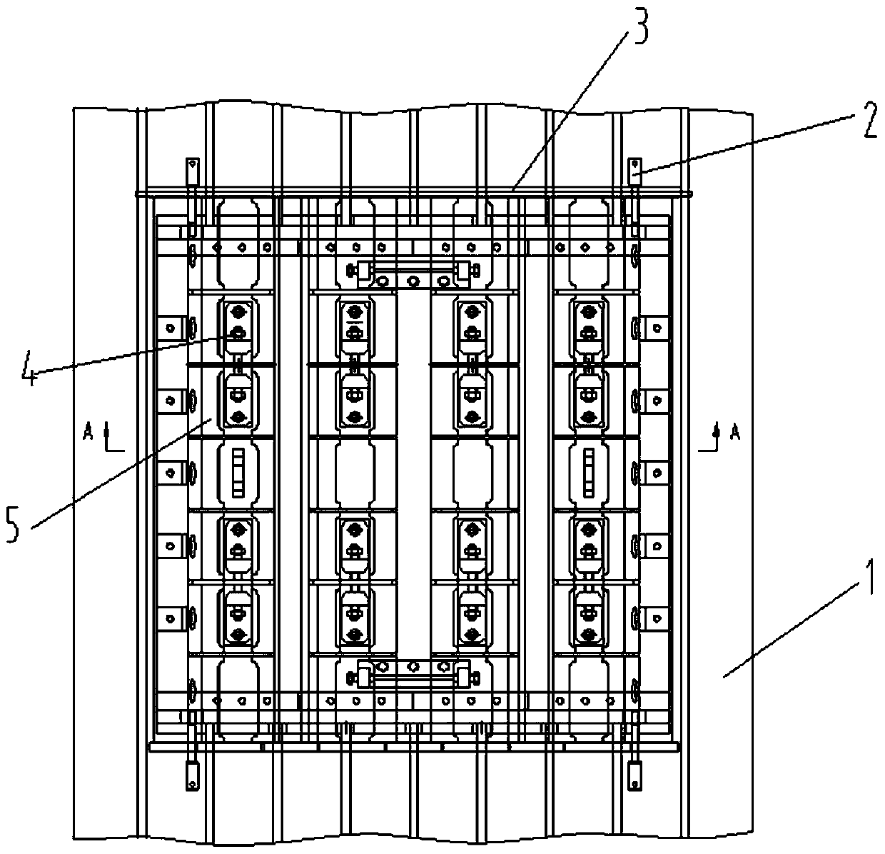
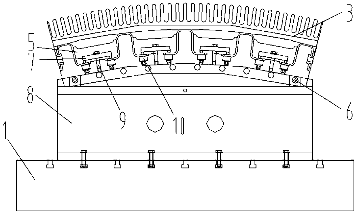
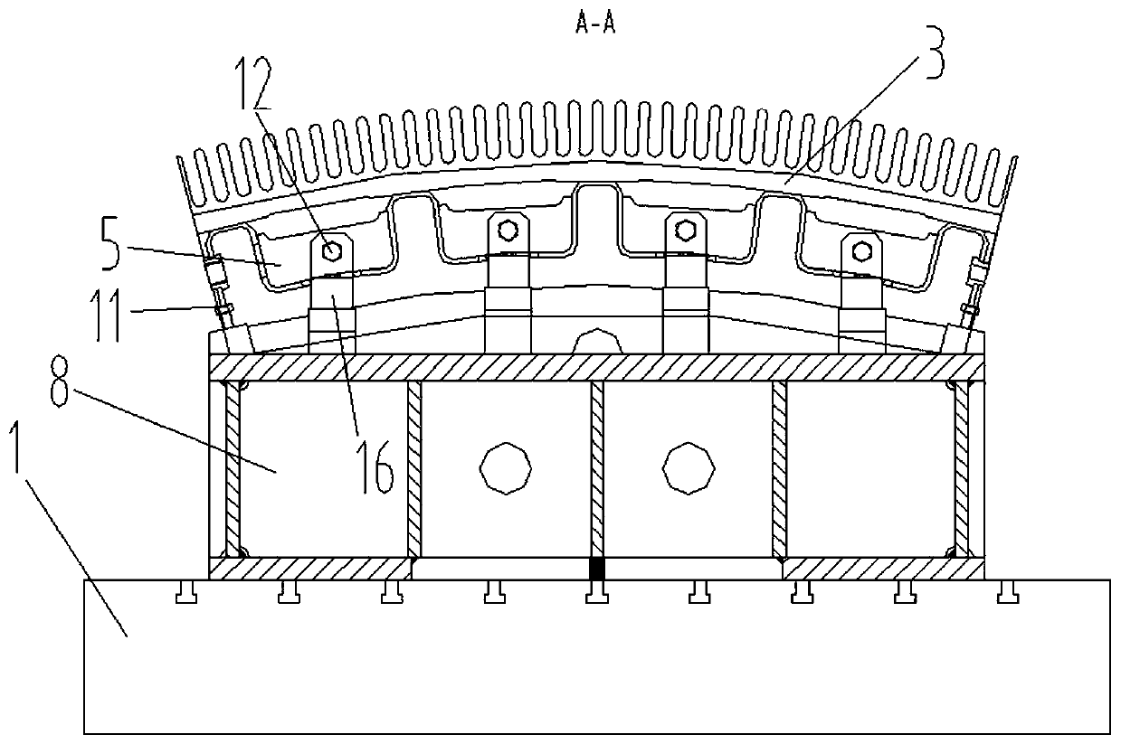
[0024] The present invention is described in further detail now in conjunction with accompanying drawing. The drawings are all simplified schematic diagrams, which only illustrate the basic structure of the present invention in a schematic manner, so they only show the configurations related to the present invention.

[0025] In the description of the invention, it should be noted that the terms "upper", "lower", "inner", "outer", "front end", "rear end", "both ends", "one end", "another end" etc. The indicated orientation or positional relationship is based on the orientation or positional relationship shown in the drawings, and is only for the convenience of describing the present invention and simplifying the description, rather than indicating or implying that the referred device or element must have a specific orientation, or in a specific orientation. construction and operation, therefore, should not be construed as limiting the invention.

[0026] In the description of...


PUM


Abstract

The invention discloses a stator section machining clamping device and a clamping method. The stator section machining clamping device comprises a milling support which is installed on a gantry milling workbench through bolts, a plurality of concave cavities are evenly formed in the outer surface of a stator section, a plurality of evenly-distributed transverse plates are arranged in the concave cavities, and the two ends of each transverse plate are fixedly connected with the side walls of the concave cavities; a plurality of pairs of top heads, a plurality of pairs of nut seats, a pluralityof supporting bolts, two adjusting frames and at least four first positioning holes are arranged on the milling support; and each pair of top heads support the inner walls of the concave cavities, each pair of nut seats top support the transverse plates, the adjustment frames support the side walls of the concave cavities, and the first positioning holes achieve positioning installation. Furthermore, the stator section can be supported, fixed and accurately positioned, the central symmetry degree of the stator section is guaranteed, meanwhile, the device does not adopt vertical clamping, secondary turn-over machining can be avoided, the labor intensity is reduced, and the working efficiency is improved.

Description

technical field [0001] The invention relates to the field of machining tooling for a stator section of a wind power generator, in particular to a clamping device and a clamping method for machining a stator section. Background technique [0002] The stator is an important core component of wind power generation equipment. In the past, most of the wind power field used steel structures or cast iron parts. With the continuous expansion of offshore direct-drive high-power wind turbines, it has now expanded to more than 10MW, and the diameter of the stator frame is getting smaller and smaller. The bigger it is, the integral stator structure is no longer suitable for the needs of production, transportation and maintenance. It is necessary to adopt a split structure, and at the same time, it is necessary to control the weight of the parts, that is, the parts are welded into components, tempered and machined. ; and the steel structure is characterized by poor rigidity of the workpi...

Claims


Application Information

Patent Timeline
Patent Type & Authority Applications(China)
IPC IPC(8): B23Q3/06B23C3/00
CPCB23C3/00B23Q3/062
Inventor 徐建华胡震
Owner JIANGSU ZHENJIANG NEW ENERGY EQUIP
Why Eureka
Try Eureka