
Cable radial cutting system and stress cone machining device with same

A cutting tool and cable technology, applied in metal processing equipment, metal processing machinery parts, manufacturing tools, etc., can solve the problem of inability to meet the processing requirements of reaction force cones of different sizes, and achieve the effect of cutting processing

Pending Publication Date: 2020-08-14
国网浙江省电力有限公司双创中心 +1
View PDF0 Cites 4 Cited by
  • Summary
  • Abstract
  • Description
  • Claims
  • Application Information

AI Technical Summary

Problems solved by technology

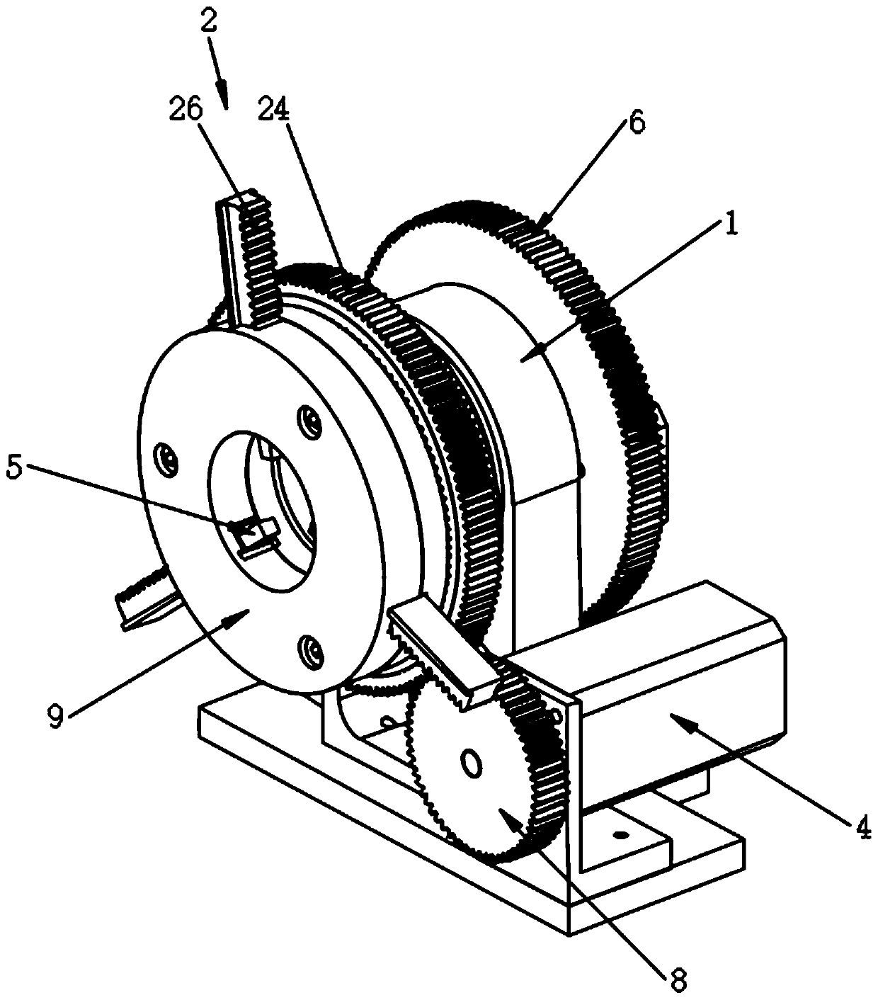
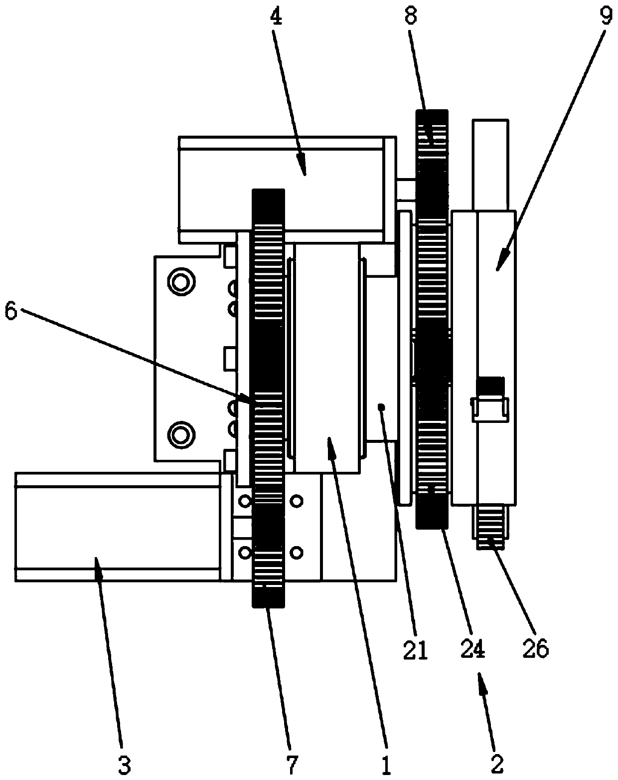
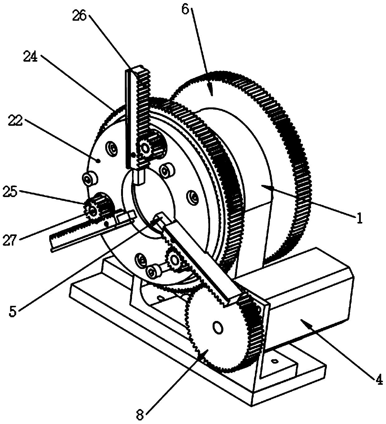
[0004] The purpose of the present invention is to provide a cable radial cutting system and its reaction force cone processing equipment to solve the problem that the existing cutting equipment cannot meet the processing requirements for reaction force cones of different sizes

Method used


Image

  • Cable radial cutting system and stress cone machining device with same
  • Cable radial cutting system and stress cone machining device with same
  • Cable radial cutting system and stress cone machining device with same

Examples


Embodiment Construction

[0023] The present invention will be further described in detail below in conjunction with the accompanying drawings and embodiments. It should be understood that the specific embodiments described here are only used to explain the present invention, but not to limit the present invention. In addition, it should be noted that, for the convenience of description, only some structures related to the present invention are shown in the drawings but not all structures.

[0024] In the description of the present invention, unless otherwise clearly specified and limited, the terms "connected", "connected" and "fixed" should be understood in a broad sense, for example, it can be a fixed connection, a detachable connection, or an integrated ; It can be a mechanical connection or an electrical connection; it can be a direct connection or an indirect connection through an intermediary, and it can be the internal communication of two components or the interaction relationship between two ...


PUM


Abstract

The invention belongs to the field of cable machining equipment, and discloses a cable radial cutting system and a stress cone machining device with the same. The cable radial cutting system comprisesa cutting support, a planetary gear set, a first driving part, a second driving part, and a cutter, wherein the planetary gear set, the first driving part and the second driving part are all mountedon the cutting support, the cutter is driven by the planetary gear set to rotate and move in a radial direction, and the first driving part and the second driving part jointly drive the planetary gearset to rotate. According to the system, the first driving part and the second driving part jointly drive the planetary gear set to rotate, so that the planetary gear set drives the cutter to rotate and move in the radial direction according to needs, and the cutting machining on stress cones with different sizes can be met.

Description

technical field [0001] The invention relates to the field of cable processing equipment, in particular to a cable radial cutting system and reaction force cone processing equipment with the same. Background technique [0002] High-voltage direct current transmission has the advantages of high transmission efficiency and low energy loss. Because it is more economical than AC transmission, it is widely used in long-distance or ultra-long-distance power transmission. However, due to the limitation of high-voltage cable manufacturing process, the maximum length of non-joint manufacturing is 10km. When ultra-long-distance transmission is to be realized, a single cable joint needs to be processed so that multiple cables can be spliced ​​together. At the cable joint, due to the two different insulating materials of cable body insulation and additional insulation, the electric field distribution is different from that of the cable body, so that a certain potential difference is ge...

Claims


Application Information

Patent Timeline
IPC IPC(8): B23Q5/04B23Q5/027
CPCB23Q5/048B23Q5/027
Inventor 王晓建陈振胥晶钦伟勋叶克勤韦柳培徐勇生沈晓斌杨旭强吴潇潇柴洁周峰沈雄章沈锴
Owner 国网浙江省电力有限公司双创中心
Learn More