
Split drilling tool connection structure for high-speed machining

A drilling tool and connection structure technology, applied in the direction of tool joints, stone processing tools, drilling tool accessories, etc., can solve the problems of asymmetric overall structure, reduce the strength of the connection structure, limit the drilling speed, etc., to ensure accuracy and Circumferential strength, improve the overall dynamic balance, avoid the effect of tool eccentricity

Active Publication Date: 2020-07-03
DALIAN UNIV OF TECH +1
View PDF8 Cites 0 Cited by
  • Summary
  • Abstract
  • Description
  • Claims
  • Application Information

AI Technical Summary

Problems solved by technology

However, this structure requires extremely high machining accuracy, and additional washers and gears also greatly increase the manufacturing cost, and the control bolt is placed on one side, resulting in asymmetrical overall structure, which seriously affects the dynamic balance of the drill bit and limits the drilling speed. Suitable for high-speed drilling of processed materials
At the same time, there is also a replaceable drill bit proposed by Iscar, which is connected by the interference fit between the convex groove of the cutting drill tip and the groove of the drill shank. The groove is positioned in the circumferential direction, but due to the influence of cutting heat during processing, the connection structure will repeatedly expand with heat and contract with cold, reducing the strength of the connection structure
It can be seen that the connection structure of the existing split drilling tool is still unable to meet the processing requirements of processing materials, especially CFRP and CFRP and metal laminates, for high-speed drilling and hole making.

Method used


Image

  • Split drilling tool connection structure for high-speed machining
  • Split drilling tool connection structure for high-speed machining
  • Split drilling tool connection structure for high-speed machining

Examples


specific Embodiment 1

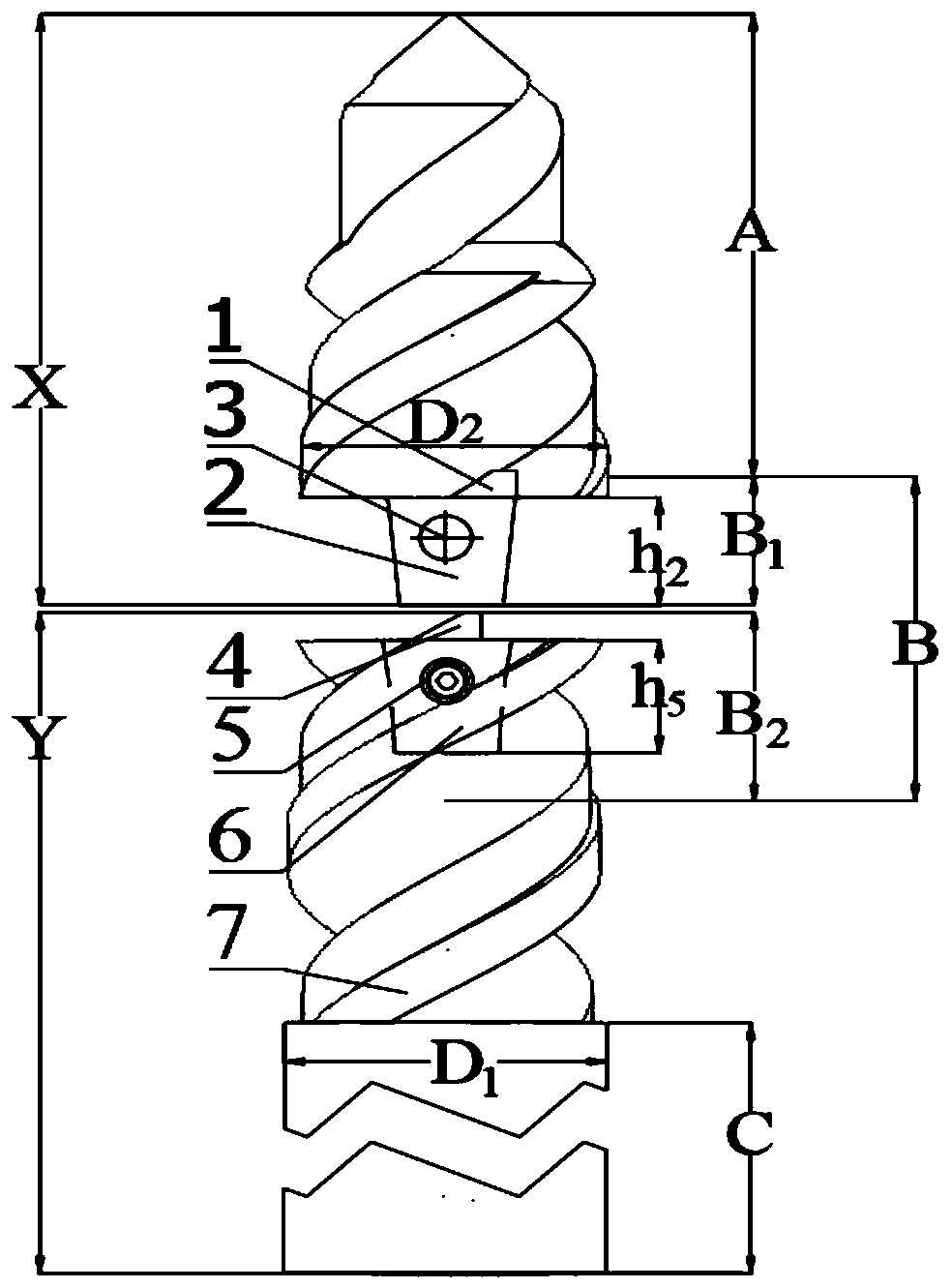
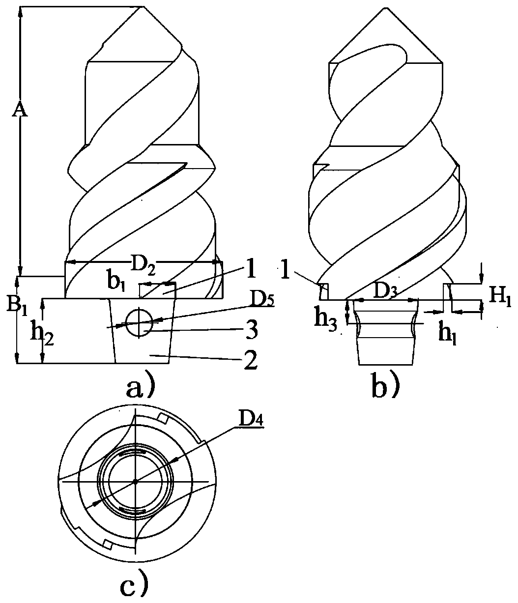
[0017] Specific embodiment 1, using CFRP as the material to be processed, the cutting part A adopts a double-stepped micro-tooth structure, the first step diameter is 7mm, the drill tip angle is 90°, the length is 8.5mm, and the second step diameter is the final hole diameter D 2 =10mm, the apex angle of the second stepped cutting edge is 90°; core thickness D 4 = 4.5 mm.

[0018] Drill point connection part B 1 The outer profile is processed with a concave ring groove 1 and a conical frustum 2, and the thickness of the concave ring groove is h 1 =0.5mm, width b 1 =2mm, depth H of concave ring groove 1 = 1mm. A round hole 3 is processed on the frustum 2, and the diameter D of the large circle of the frustum 2 is 3 =4mm, height h of frustum 2 2 =4mm, the centerline of the circular hole 3 and the large circle diameter D of the frustum of the cone 2 3 distance h 3 = 2mm, the taper of the truncated cone 2 is 1:6, and the diameter of the circular hole 3 is D 5 = 1.6 mm.

...

specific Embodiment 2

[0022] Specific embodiment 2, with the CFRP / aluminum alloy laminated structure as the material to be processed, the tool tip X is a combination of 120° and 140° double-vertex angle drill tip form, and the diameter of the final hole is D 2 = 10mm;

[0023] Drill tip connection part B 1 The outer profile is processed with a concave ring groove 1 and a conical frustum 2, and the thickness of the concave ring groove is h 1 =0.5mm, width b 1 =2mm, depth H of concave ring groove 1 = 1 mm. A round hole 3 is processed on the frustum 2, and the diameter D of the large circle of the frustum 2 is 3 =4mm, height h of frustum 2 2 =4mm, the centerline of the circular hole 3 and the large circle diameter D of the frustum of the cone 2 3 distance h 3 = 2mm, the taper of the truncated cone 2 is 1:6, and the diameter of the circular hole 3 is D 5 = 1.6 mm.

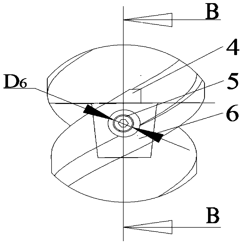
[0024] Shank connection part B 2 with B 1 Matching, the size of the boss 4 matches the groove 1, and the diameter of the left a...


PUM


Abstract

The invention relates to a split drilling tool connection structure for high-speed machining, belongs to the technical field of mechanical processing, and relates to a split drilling tool connection structure for high-speed machining. The split drilling tool connection structure has two parts which are a drill tip for cutting and a drill shank for chip removal and clamping. The drill tip is divided into a drilling part and a drill tip connection part, the drill shank is divided into a drill shank connection part and a clamping area, and the drill tip connection part and the drill shank connection part form a quick-change connection area. According to the split drilling tool connection structure, the connection of the drill tip and the drill shank can be realized without damaging a chip groove and a cutting edge, the height of the drill tip and a drill body are ensured to be concentric by using equal cone surfaces, and the mirror images on the two sides of the connection structure are maintained to be symmetric in height, and the stability of a split tool in drilling at high speed is ensured; the connection structure is versatile, one drill shank can be matched with main bodies of drill tips of various types, replacing is simple and convenient, the split drilling tool connection structure is suitable for various machining environments, and the engineering application prospects are good.

Description

technical field [0001] The invention belongs to the technical field of machining, and relates to a split drilling tool connection structure for high-speed machining. Background technique [0002] In order to further improve the economy and service performance of aerospace and other high-end equipment, it is an effective way to develop low-damage and low-cost processing technology in the equipment manufacturing process. As the main processing form, hole making is a huge number in aviation equipment. For example, in order to realize the assembly connection between components on a B747 passenger plane, more than 3 million assembly holes must be processed, and CFRP is often involved in hole making. Processing materials. This will scrap a considerable number of drilling tools, and in the scrapped drilling tools, most of the wear occurs at the drill tip position, and there is not much wear at the drill shank, so this also causes about 90% of the tool Materials are not used effec...

Claims


Application Information

Patent Timeline
IPC IPC(8): B28D1/14B23B51/00B23B51/12B26F1/16
CPCB23B51/00B23B51/12B26F1/16B28D1/146
Inventor 王福吉刘欣赵猛付饶王振宇仇沈
Owner DALIAN UNIV OF TECH
Learn More