Cast-weld combined type cable saddle forming structure

A forming structure and combined technology, applied in bridge parts, bridges, buildings, etc., can solve the problems of large welding residual stress, reducing the compressive strength of the joint between the saddle and the saddle, and adverse effects on the structural performance of the cable saddle. , to achieve the effect of high molding quality, easy casting defects, and enhanced bonding reliability

Pending Publication Date: 2020-08-14
DEYANG TIANYUAN HEAVY IND +1
View PDF0 Cites 0 Cited by
  • Summary
  • Abstract
  • Description
  • Claims
  • Application Information

AI Technical Summary

Problems solved by technology

[0004] The penetration welding forming structure of the cast-welding combined cable saddle makes a large amount of penetration welding between the saddle head of the casting structure and the saddle of the weldment structure, and the welding residual stress caused by these penetration welding is partial If it is large, it will directly reduce the bearing strength of the joint between the saddle head and the saddle, which will have an adverse effect on the overall structural performance of the cable saddle

Method used


Image

  • Cast-weld combined type cable saddle forming structure
  • Cast-weld combined type cable saddle forming structure
  • Cast-weld combined type cable saddle forming structure

Examples


Embodiment 1

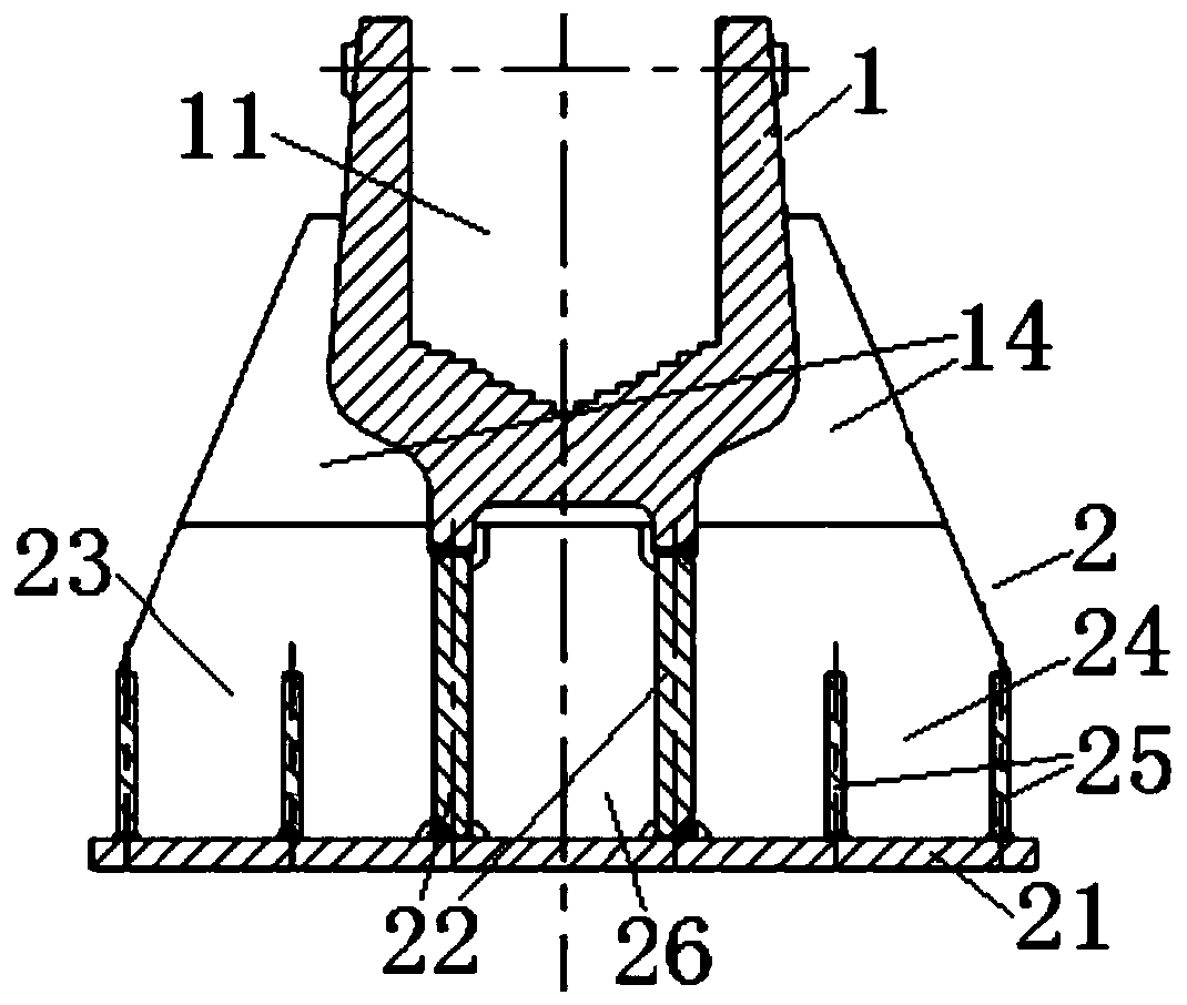
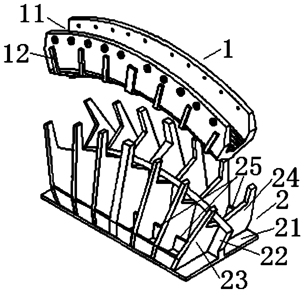
[0028] see figure 2 , image 3 , Figure 4 , Figure 5 and Figure 6 As shown, the present invention is a main cable saddle for suspension bridge engineering, which includes a saddle head 1 of a casting structure and a saddle 2 of a weldment structure.

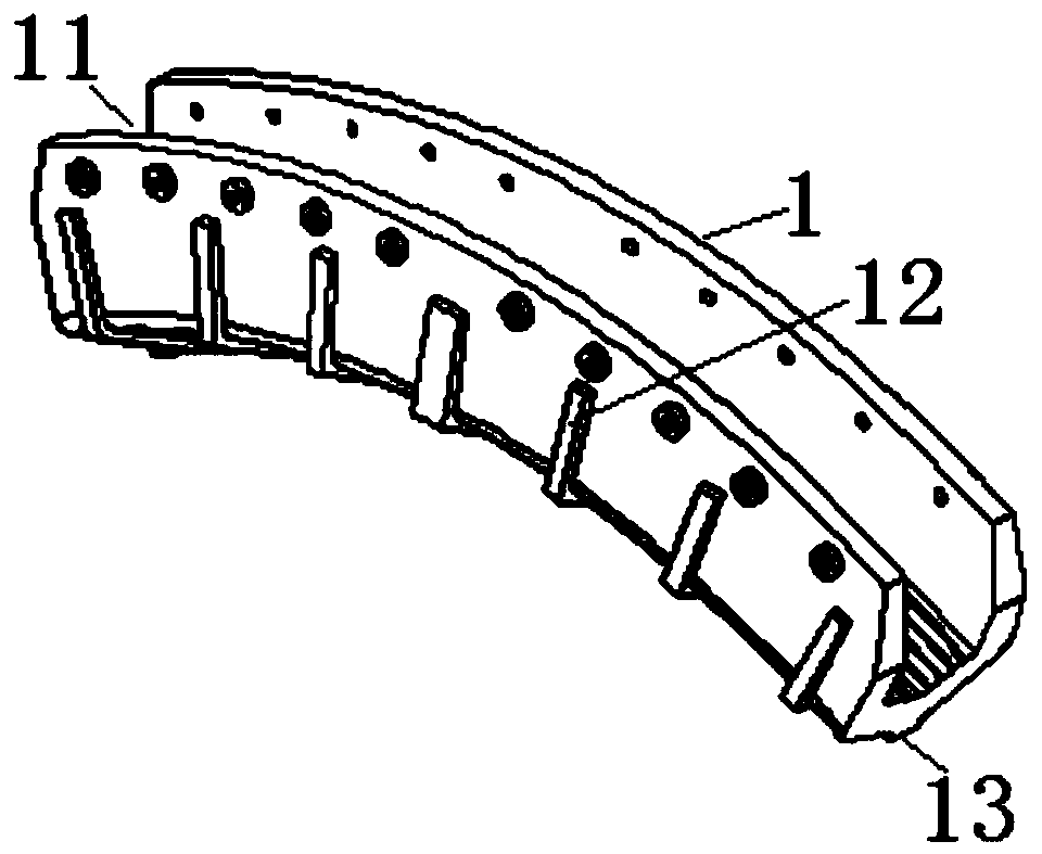
[0029] Among them, there is a saddle groove 11 along the longitudinal direction of the saddle head 1 with a concave structure and a curved bottom to support the main cable. The saddle groove 11 on the saddle head 1 is only corresponding to the height of the saddle head 1. direction of the two-dimensional saddle groove structure.

[0030] The bottom central area of ​​the saddle head 1 has a longitudinal beam 13 protruding downward along the longitudinal direction of the saddle head 1 , and the thickness center of the longitudinal beam 13 basically corresponds to the width center of the saddle groove 11 on the saddle head 1 .

[0031] Both sides of the outer periphery of the saddle head 2 have a plurality of protruding rib...

Embodiment 2

[0046] The other content of this embodiment is the same as that of Embodiment 1, except that: the longitudinal beams protruding downwards from the bottom of the saddle head are arranged at two intervals; correspondingly, the longitudinal ribs on the saddle are arranged at intervals. Two sets of cloth, there are multiple sets of middle transverse ribs between these two sets of longitudinal ribs, and each set of middle transverse ribs is closely fitted with the pommel head by polishing, and supplemented by fillet welding, similar to figure 1 shown.

Embodiment 3

[0048] The other content of this embodiment is the same as that of Embodiment 1, the difference is that only the grinding and top tight fit between the saddle head and the saddle seat, without the assistance of fillet welding.


PUM


Abstract

The invention discloses a cast-weld combined type cable saddle forming structure which comprises a saddle head of a casting structure and a saddle of a weldment structure. The saddle head is assembledon the saddle through a polishing abutting fit structure. The saddle head of the casting structure and the saddle of the weldment structure are assembled together through the polishing abutting fit structure, complex, high-difficulty and high-residual-stress penetration welding treatment does not need to be adopted, assembling and forming are convenient, bearing strength of the joint between thesaddle head and the saddle can be greatly improved, and then overall structural stability of the cable saddle is improved.

Description

technical field [0001] The invention relates to a cable saddle for suspension bridge engineering, in particular to a main cable saddle, in particular to a casting and welding combined cable saddle forming structure. Background technique [0002] In suspension bridge engineering, a saddle is a permanent, large steel member used to support the main cables. Common cable saddles are all-cast, all-welded and cast-welded combined. Among them, the cast-welded combined cable saddle is formed by casting the saddle head with complex structure shape with cast steel, and welded the saddle with simple structure and high-quality steel plate to form it, which effectively absorbs the full-cast and fully-welded cable saddles. The technical advantages of saddles shield their respective technical deficiencies, and the overall comprehensive performance is high. [0003] Common casting and welding combined cable saddles such as figure 1 As shown, it includes a saddle head 1 of a casting struc...

Claims


Application Information

Patent Timeline
Patent Type & Authority Applications(China)
IPC IPC(8): E01D19/14
CPCE01D19/14
Inventor 黄安明万田保陈龙王忠彬张旭
Owner DEYANG TIANYUAN HEAVY IND
Why Eureka
Try Eureka