Collecting pressure line for fuel injection system of internal combustion engine

一种燃料喷射系统、压力管路的技术,应用在燃料喷射装置、特殊燃料喷射装置、装料系统等方向,能够解决燃料供应不足等问题,达到减少燃烧的效果

Active Publication Date: 2020-08-14
DR ING H C F PORSCHE AG
View PDF8 Cites 0 Cited by
  • Summary
  • Abstract
  • Description
  • Claims
  • Application Information

AI Technical Summary

Problems solved by technology

Due to the different injection times of the injectors accommodated in the manifold pressure line, pressure fluctuations occur in the manifold pressure line, which can lead to insufficient fuel supply of the injectors and thus the cylinders

Method used


Image

  • Collecting pressure line for fuel injection system of internal combustion engine
  • Collecting pressure line for fuel injection system of internal combustion engine
  • Collecting pressure line for fuel injection system of internal combustion engine

Examples


Embodiment Construction

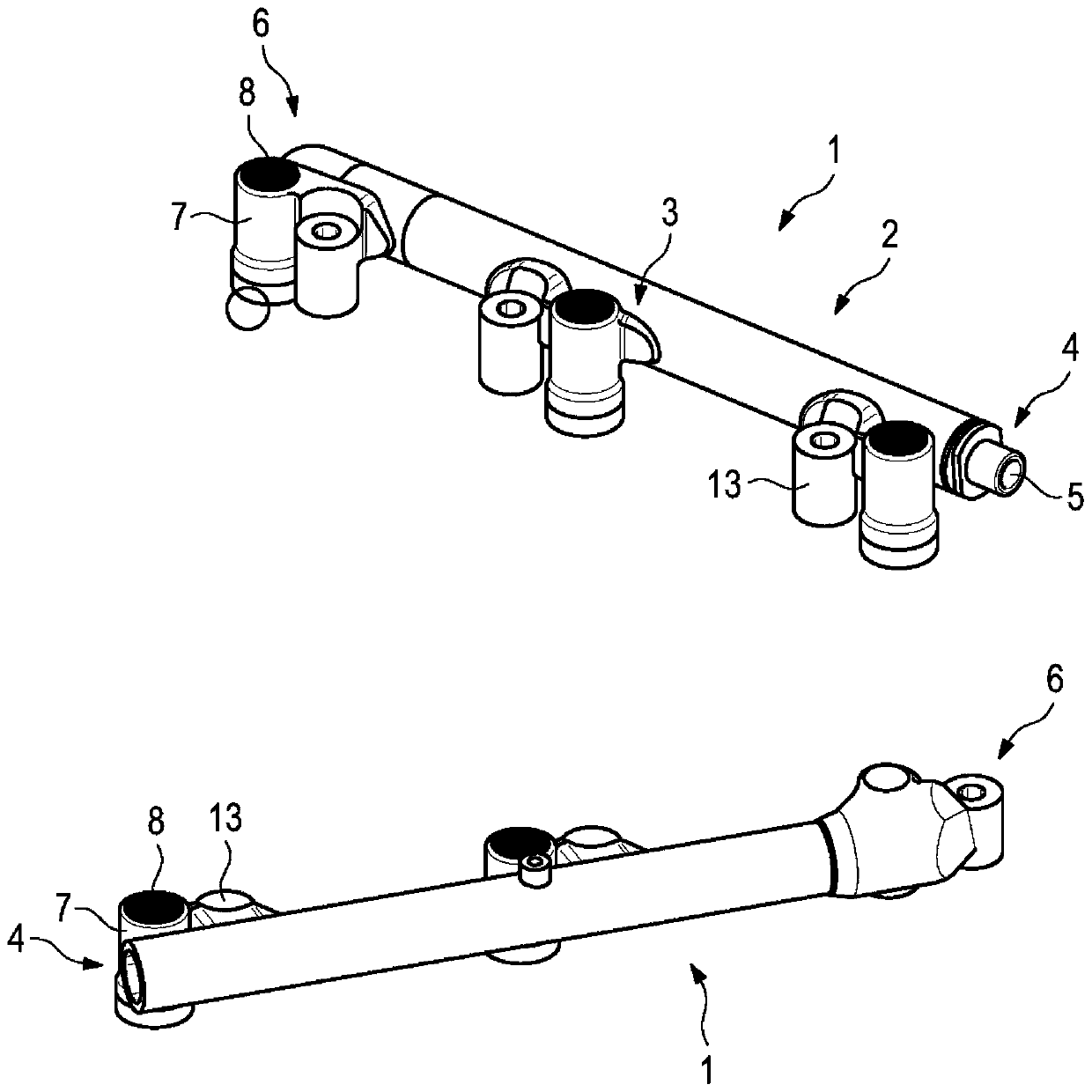
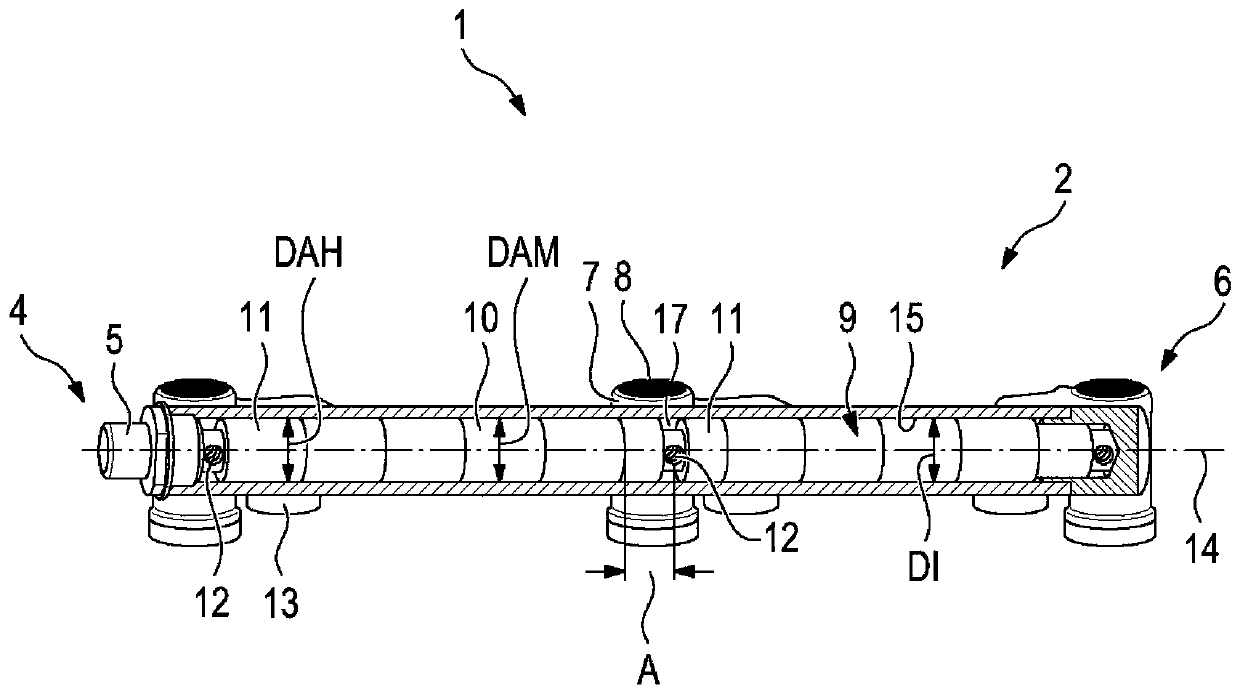
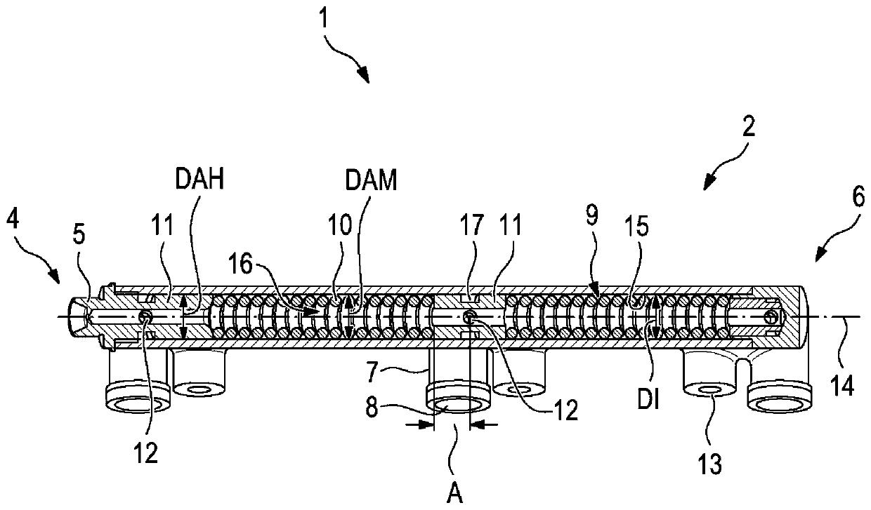
[0025] according to figure 1 The constructed manifold pressure line 1 according to the invention of the fuel injection system 2 is designed for an internal combustion engine (not shown in detail) with two cylinder banks. The manifold pressure line 1 is designed in the form of a supply line (a so-called fuel rail or fuel supply line) and has flow-through receiving openings 3 corresponding to the number of cylinders to be supplied, which are each equipped with ( not shown in detail) injector. In the present embodiment, the manifold pressure line 1 has three receiving openings 3 , so that three cylinders of the internal combustion engine are supplied with fuel via the manifold pressure line 1 . Likewise, it is also possible that the collecting pressure line is designed for feeding two or four or more injectors and accordingly has two or four or more receiving openings 3 .

[0026] The manifold pressure line 1 interconnects a fuel pump (not shown in detail) in the form of a high...


PUM


Abstract

The invention relates to a collecting pressure line for a fuel injection system of an internal combustion engine. A collecting pressure line (1) for a fuel injection system of an internal combustion engine has a flow-traversable interior (9). The collecting pressure line (1) has at least one injector that is flow-traversable with the aid of a through-flow opening (8). Fluid present in the collecting pressure line (1) is injected with the aid of the injector into a combustion chamber of the internal combustion engine. An elastic member (10) is formed in the interior (9) and is designed to be flow-traversable while bearing against a line inner wall (15) and spaced apart from the through-flow opening (8).

Description

technical field [0001] The invention relates to a manifold pressure line for a fuel injection system of an internal combustion engine according to the preamble of claim 1 . Background technique [0002] Collecting pressure lines of fuel injection systems for injecting fuel for internal combustion engines are known. Each cylinder of an internal combustion engine is equipped with an injector which is connected in a passable manner to a manifold pressure line (commonly referred to as a fuel rail or fuel supply line), wherein the manifold pressure line is equipped with at least Two injectors. A pressurized fluid to be fed to the cylinder for combustion is formed in the manifold pressure line, which fluid is fed to the cylinder by the injector according to the respective injection time of the injector. Due to the different injection times of the injectors accommodated in the manifold pressure line, pressure fluctuations occur in the manifold pressure line which can lead to unde...

Claims


Application Information

Patent Timeline
Patent Type & Authority Applications(China)
IPC IPC(8): F02M55/02
CPCF02M55/025F02M2200/315F02M2200/9015F02M55/02F02M55/04
Inventor J·格林贝格尔H·沃斯
Owner DR ING H C F PORSCHE AG
Why Eureka
Try Eureka