Spiral volute of centrifugal fan

A centrifugal fan and volute technology, applied in mechanical equipment, machines/engines, liquid fuel engines, etc., can solve the problems of reduced effective flow area of ​​volute and increased diffusion loss

Inactive Publication Date: 2020-08-14
XI AN JIAOTONG UNIV
View PDF5 Cites 2 Cited by
  • Summary
  • Abstract
  • Description
  • Claims
  • Application Information

AI Technical Summary

Problems solved by technology

[0005] In actual use, because the cross-sectional area of ​​the air flow changes suddenly when it flows out of the impeller outlet, and because the radial height of the volute is too small, the air flow violently impacts the side wall of the volute, forming a huge vortex in the cavity on both sides of the volute, so that the entire The fluid in the flow channel of the volute advances in a spiral form, which will greatly reduce the effective flow area of ​​the volute and increase the diffusion loss

Method used


Image

  • Spiral volute of centrifugal fan
  • Spiral volute of centrifugal fan
  • Spiral volute of centrifugal fan

Examples


Embodiment Construction

[0022] The technical solutions in the embodiments of the present invention are clearly and completely described below in conjunction with the accompanying drawings in the embodiments of the present invention. Obviously, the described embodiments are only part of the embodiments of the present invention, not all of them.

[0023] Examples of the described embodiments are shown in the drawings, wherein like or similar reference numerals designate like or similar elements or elements having the same or similar functions throughout. The embodiments described below by referring to the figures are exemplary and are intended to explain the present invention and should not be construed as limiting the present invention.

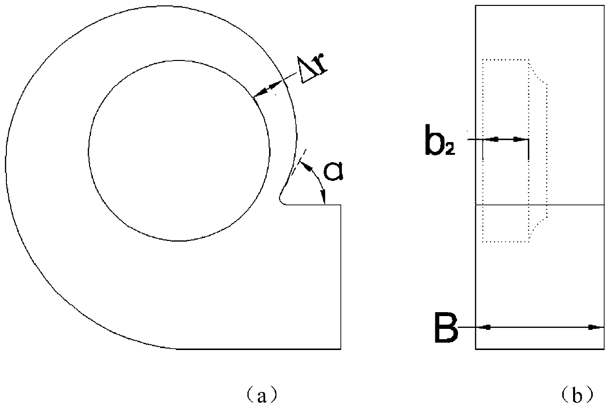
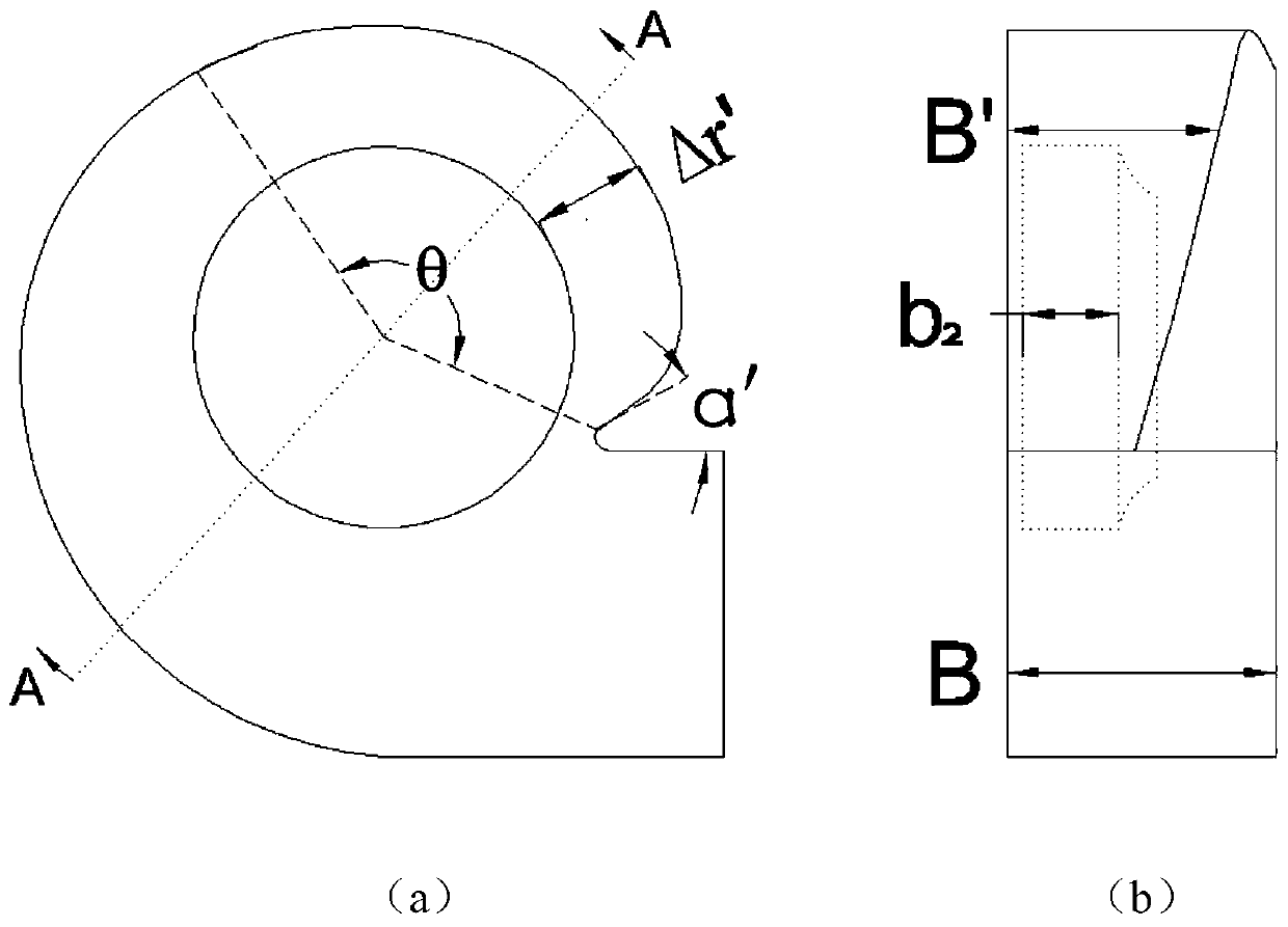
[0024] refer to Figure 4 , a spiral volute of a centrifugal fan. Compared with the traditional volute, the positions of the volute and the volute tongue 2 are consistent with the conventional volute, but the width of the volute is not fixed, but changes. The width o...


PUM


Abstract

The invention provides a spiral volute of a centrifugal fan. The volute is in the minimum width at the position of a volute tongue, and the width thereof is gradually increased along the flowing direction and, at a certain angle, is equal to the width of an opening of the volute. The radius of the profile of the volute is increased near the volute tongue, i.e. the radial height of the volute is increased. Through the arrangement that a spiral volute structure is formed by changing heights of the volute, because of the increased radial height, an air flow at the opening of the volute is not prone to impacting the wall face of the volute in the radial direction; because the width of the volute is decreased near the volute tongue, the degree of diffusion in the width direction of the air flowwhich enters from an impeller into the volute is decreased; and therefore, diffusion loss and impact loss are reduced and the original status is recovered. The spiral volute of the centrifugal fan isbeneficial to improving efficiency of the centrifugal fan.

Description

technical field [0001] The invention relates to the technical field of fans, in particular to a spiral volute of a centrifugal fan. Background technique [0002] Traditional centrifugal fan volute structure such as figure 1 Shown, the volute width B is a constant value. The width of the volute is about 2.5 times the width of the impeller outlet. After the high-speed fluid at the outlet of the impeller enters the volute, a large diffusion loss is caused due to the sudden change in the cross-sectional area. And the cavity between the wheel cover side of the volute and the wheel cover will form a huge vortex area. [0003] like figure 1 As shown, because the radial height Δr of the volute is too small, the angle α between the tangent at the volute tongue and the horizontal direction is too large, the airflow at the outlet of the impeller will impact the side plate of the volute, causing impact loss and increasing the noise . [0004] Theoretical calculations and experimen...

Claims


Application Information

Patent Timeline
Patent Type & Authority Applications(China)
IPC IPC(8): F04D29/42F04D29/66
CPCF04D29/4226F04D29/4233F04D29/667
Inventor 张义云田俊俊
Owner XI AN JIAOTONG UNIV
Why Eureka
Try Eureka