
Support part clamp

A technology of parts and fixtures, which is applied in the field of mechanical processing, can solve the problems of high manufacturing cost and storage cost of assembly fixtures, unstable assembly quality of assembly fixtures, and high labor intensity for workers to install and disassemble, so as to reduce labor intensity and simple structure , the effect of quick replacement

Inactive Publication Date: 2020-08-18
SHENYANG AIRCRAFT CORP
View PDF6 Cites 0 Cited by
  • Summary
  • Abstract
  • Description
  • Claims
  • Application Information

AI Technical Summary

Problems solved by technology

[0003] The existing technology has the following problems: ①Each feature requires a set of assembly fixtures. Due to the accumulation of errors, there are a large number of reference conversion errors, which affect the position accuracy between each feature; ②The assembly fixture has unstable assembly quality and long assembly cycle. , Long production preparation time, bulky assembly fixtures, labor-intensive installation and disassembly of workers, high manufacturing costs and storage costs of assembly fixtures, etc. If the number of parts is large, this problem will be more prominent

Method used


Image

  • Support part clamp
  • Support part clamp
  • Support part clamp

Examples


Embodiment Construction

[0023] The specific embodiments of the present invention will be described in further detail below in conjunction with the accompanying drawings, so as to help those skilled in the art have a more complete and in-depth understanding of the present invention.

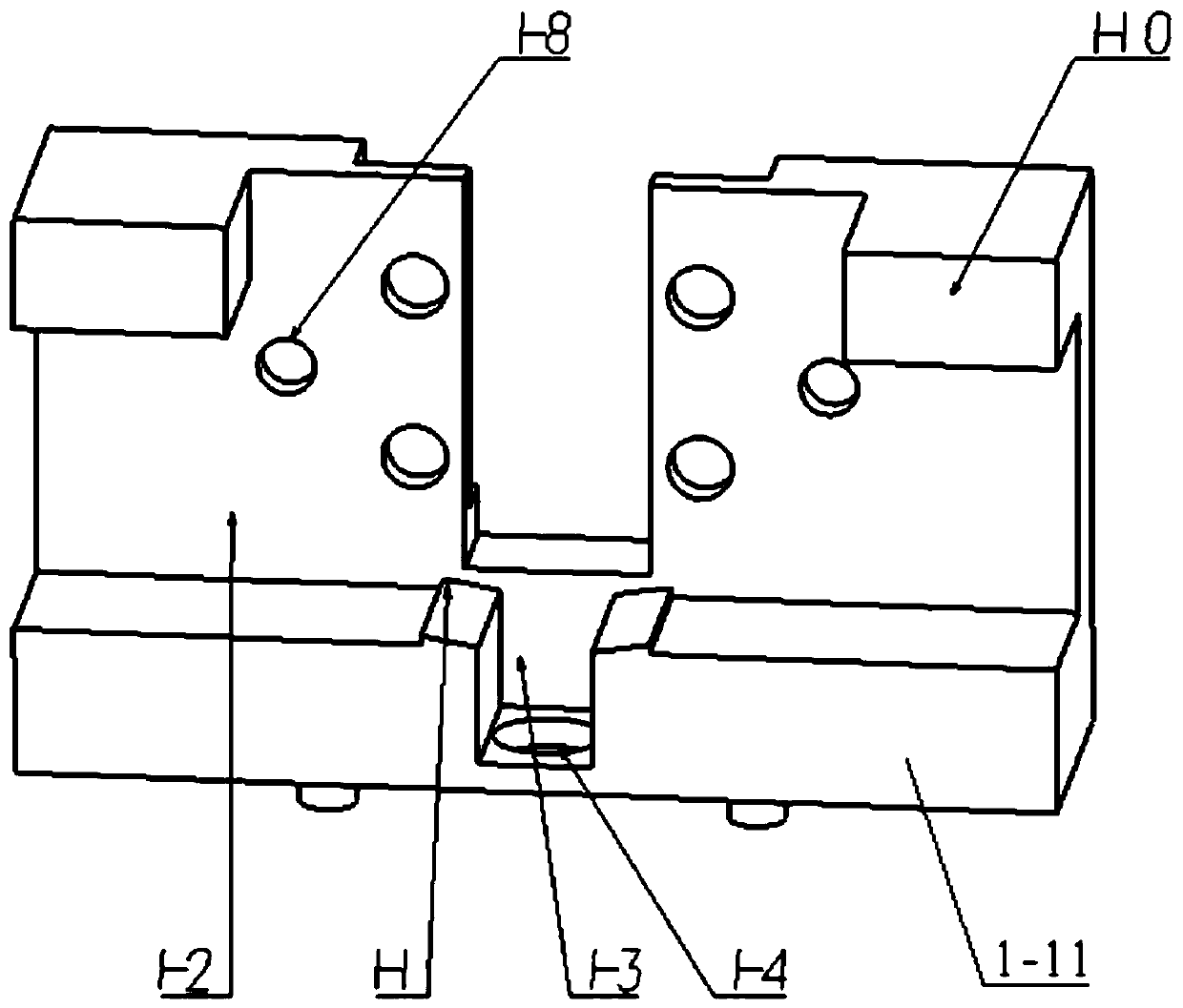
[0024] like Figure 3-Figure 6 As shown, a bracket part fixture includes a base body 1, a large drill sleeve 2, a small drill sleeve 3, a stud 4, a pressure plate 5 and a lock nut 6.

[0025] The bottom of the base 1 is provided with four pillars 1-9, and the top of the base 1 is provided with a boss B1-10. Boss A1-11 and surface A1-2 are processed on the lower part of base body 1 . The center of the boss A1-11 is processed with a V-shaped positioning surface 1-1; the bracket part to be processed is put into the base body 1, the surface F of the part to be processed is attached to the surface A1-2 of the base body, and the part to be processed is The surface E cooperates with the V-shaped positioning surface 1-1 to rea...


PUM


Abstract

The invention discloses a support part clamp, and belongs to the technical field of machining. The clamp comprises a base body, a large drill sleeve, small drill sleeves, studs, press plates and locking nuts. The clamp can achieve one-time clamping to complete machining of four features, and machining efficiency is high; the clamp can achieve the effects that replacement and adjusting are rapid, operation is convenient, the structure is simple, universality is good, the benchmark is uniform, and locating is accurate; and meanwhile, the manufacturing cost and the management cost are greatly saved, and the labor intensity of workers is reduced.

Description

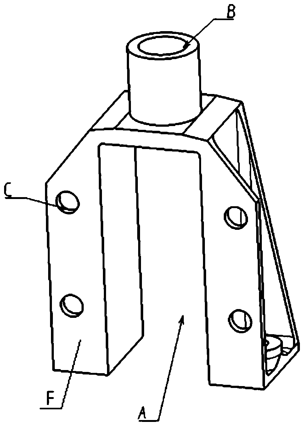
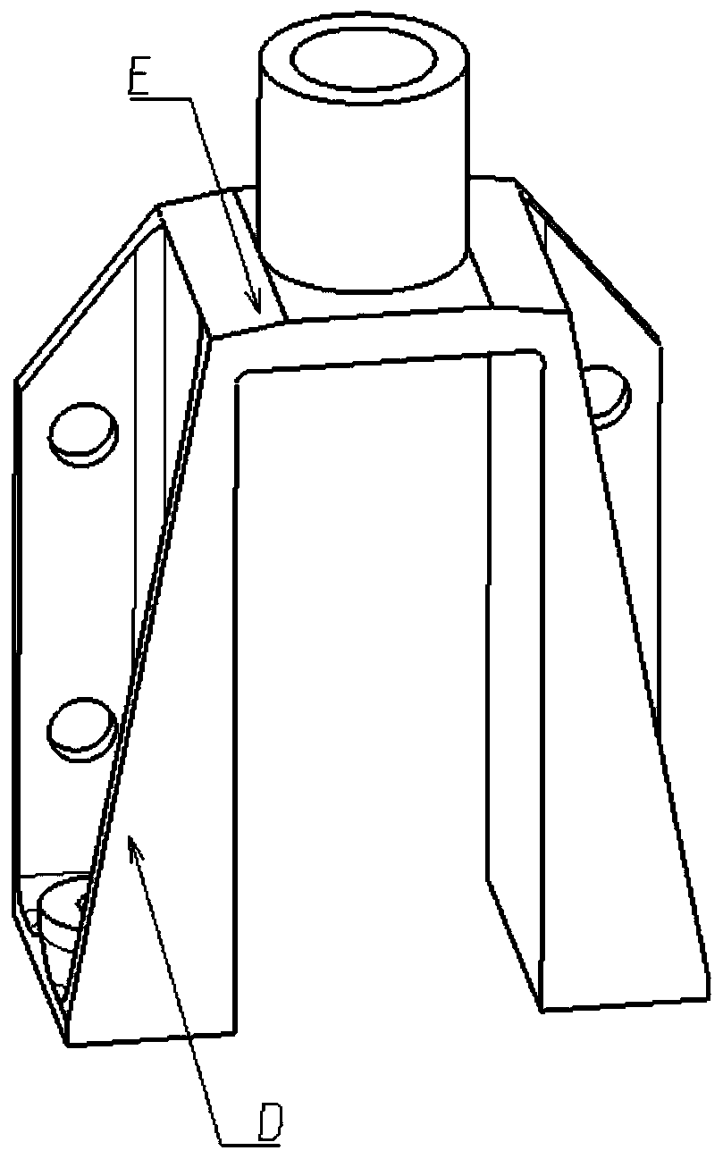
technical field [0001] The invention belongs to the technical field of mechanical processing and relates to a special fixture, in particular to a fixture suitable for bracket parts. Background technique [0002] Bracket parts are widely used in the field of machining and play an important role in supporting connections, such as figure 1 , figure 2 As shown, the bracket part has a V-shaped surface E and a groove A to be processed, a hole B, a hole C and a surface D, and the groove A, the hole B, the hole C and the surface D are not on the same plane. The processing method in the prior art is as follows: first each use a set of assembled milling clamps to process groove A and surface D on a milling machine, and then each use a set of assembled drilling molds to process hole B and hole C. [0003] The existing technology has the following problems: ①Each feature requires a set of assembly fixtures. Due to the accumulation of errors, there are a large number of reference conv...

Claims


Application Information

Patent Timeline
Patent Type & Authority Applications(China)
IPC IPC(8): B23Q3/00B23B47/28
CPCB23B47/28B23B2247/12B23Q3/00B23Q2703/10
Inventor 孙捷夫薛祥友潘海
Owner SHENYANG AIRCRAFT CORP
Learn More