
Forming die for manufacturing reinforced concrete prefabricated columns of fabricated building

A technology for reinforced concrete and forming molds, applied in the direction of manufacturing tools, forming surfaces, mold trays, etc., can solve the problems of limited support force, different arrangements of steel skeletons, unevenness, etc., and achieve the effect of increasing support strength.

Active Publication Date: 2020-08-18
扬州通惠系统集成科技有限公司
View PDF6 Cites 9 Cited by
  • Summary
  • Abstract
  • Description
  • Claims
  • Application Information

AI Technical Summary

Problems solved by technology

[0003] The existing forming molds have the following disadvantages: 1. When the mold is closed, the supporting force between the side plate and the bottom plate is limited. When there is a lot of concrete poured, the side plate will be deformed due to the high pressure, so that the prefabricated column The surface after forming is not even; 2. For prefabricated columns of the same specification, the arrangement of the steel skeleton is different, and there is no corresponding end plate for the steel skeleton with different arrangements

Method used


Image

  • Forming die for manufacturing reinforced concrete prefabricated columns of fabricated building
  • Forming die for manufacturing reinforced concrete prefabricated columns of fabricated building
  • Forming die for manufacturing reinforced concrete prefabricated columns of fabricated building

Examples


Embodiment Construction

[0027] The embodiments of the present invention will be described in detail below with reference to the accompanying drawings, but the present invention can be implemented in many different ways defined and covered by the claims.

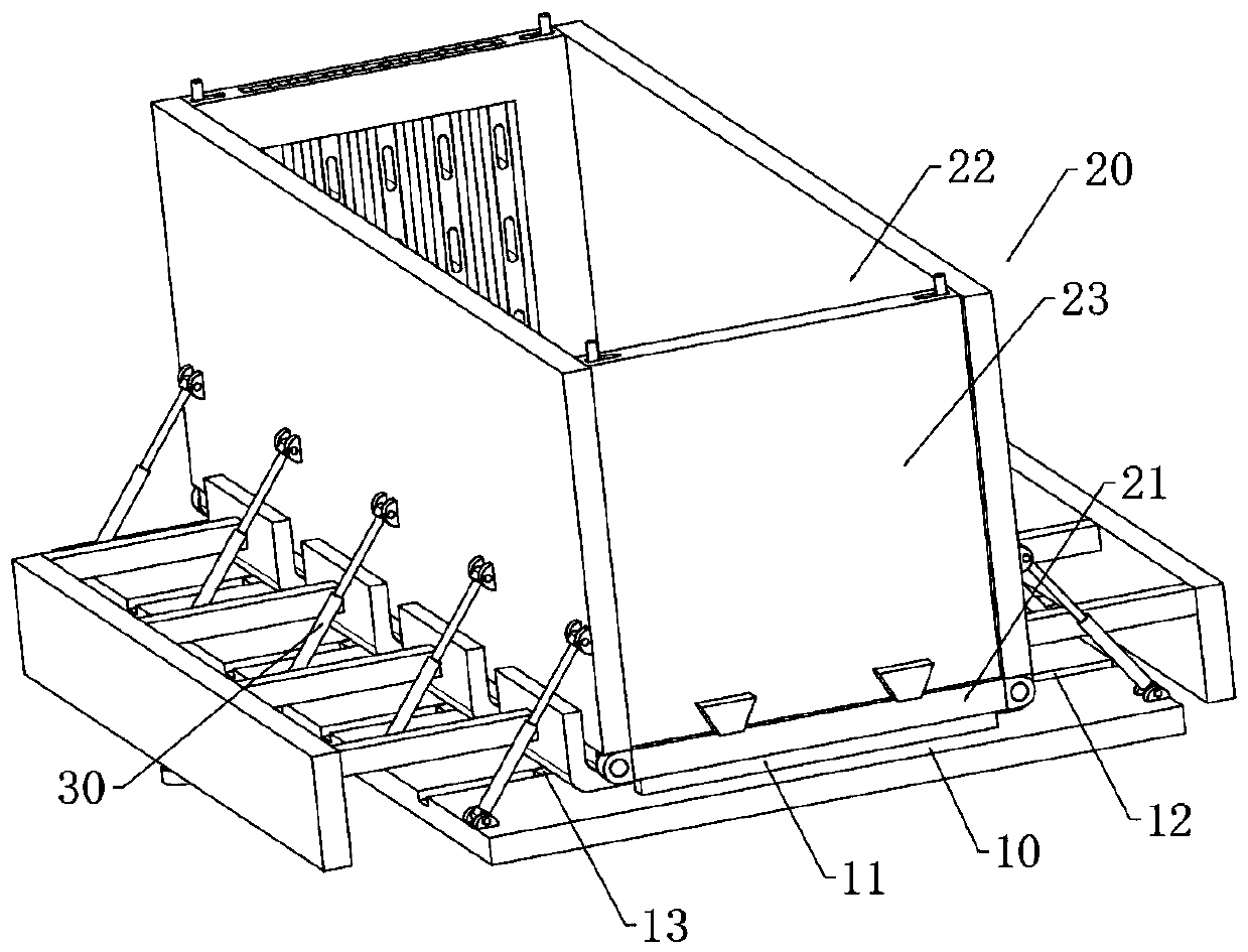
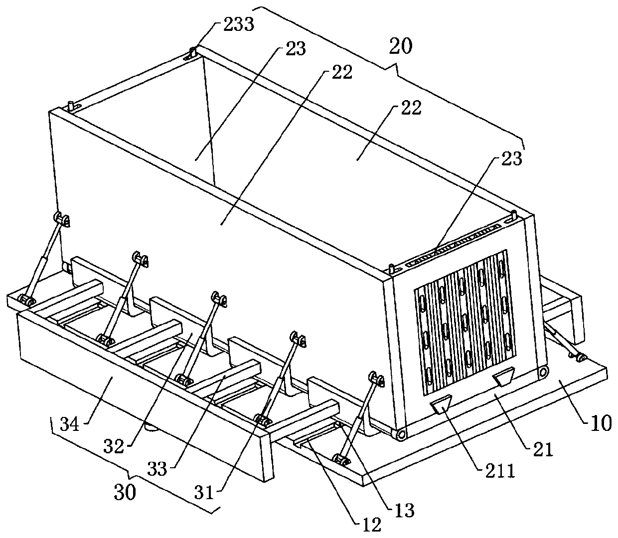
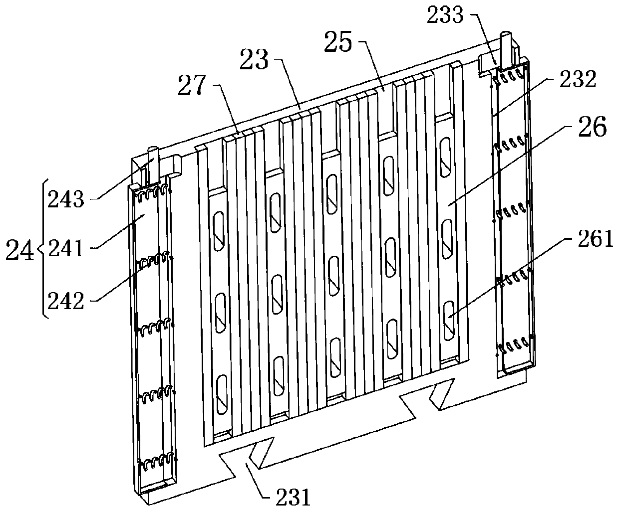
[0028] Such as Figure 1 to Figure 7 As shown, a mold for manufacturing reinforced concrete prefabricated columns of prefabricated buildings includes a workbench 10 and a mold 20 arranged above the workbench 10. The mold 20 includes a bottom plate 21 fixed on the workbench 10 and hinged on both sides of the bottom plate 21. The side plates 22 and the end plates 23 slidingly arranged at both ends of the bottom plate 21, the top of the workbench 10 are provided with support devices 30 on both sides of the bottom plate 21;

[0029] The top of the workbench 10 is provided with a support plate 11 extending along its width direction. The base plate 21 and the workbench 10 are fixedly connected by multiple sets of support plates 11. The support plates 11 a...


PUM


Abstract

The invention relates to a forming die for manufacturing reinforced concrete prefabricated columns of a fabricated building. The forming die comprises a workbench and a die arranged above the workbench, wherein the die comprises a bottom plate fixed on the workbench, side plates hinged to the two sides of the bottom plate and end plates slidably arranged at the two ends of the bottom plate, the workbench is fixedly connected with the bottom plate through supporting plates, and supporting devices are arranged at the positions, on the two sides of the bottom plate, of the top of the workbench. According to the forming die, oil cylinders and L-shaped plates which are arranged in a crossed manner are used to jointly support the side plates and the bottom plate, the supporting strength is increased, and meanwhile, the L-shaped plates can be synchronously separated under the driving of electric push rods during demoulding; and first rectangular plates and second rectangular plates are arranged on a group of end plates, the number of groups of second rectangular plates between two adjacent groups of first rectangular plates is increased or reduced to change the spacing between the first rectangular plates, and waist-shaped holes are formed at different heights of the first rectangular plates, so as to adapt to steel bar frameworks in different arrangement manners to pass through.

Description

technical field [0001] The invention relates to the technical field of prefabricated part molds, in particular to a forming mold for manufacturing reinforced concrete prefabricated columns of assembled buildings. Background technique [0002] Assembled construction refers to the transfer of a large number of on-site operations in the traditional construction method to the factory, where the building components and accessories (such as floor slabs, wall panels, stairs, balconies, etc.) are processed and manufactured in the factory, and transported to the construction site. Reliable connections are assembled and installed on site. When the prefabricated column is formed, it is necessary to first place the prepared steel skeleton in the corresponding forming mold, and then pour concrete into the mold. [0003] The existing forming molds have the following disadvantages: 1. When the mold is closed, the supporting force between the side plate and the bottom plate is limited. Whe...

Claims


Application Information

Patent Timeline
IPC IPC(8): B28B7/00B28B23/18
CPCB28B7/0002B28B7/0032B28B7/0055B28B23/18
Inventor 汤仁超邱甜甜李西华
Owner 扬州通惠系统集成科技有限公司
Learn More