
Turnover support assembly structure and assembling method thereof

A technology of overturning bracket and assembly structure, applied in the field of overturning bracket, which can solve problems such as difficult to tighten connecting bolts, and achieve the effect of high assembly efficiency and easy tightening

Pending Publication Date: 2020-08-18
DONGFENG AUTOMOBILE COMPANY
View PDF0 Cites 0 Cited by
  • Summary
  • Abstract
  • Description
  • Claims
  • Application Information

AI Technical Summary

Problems solved by technology

[0004] The purpose of the present invention is to overcome the defects and problems existing in the prior art that it is difficult to tighten the connecting bolts at the cab drop-down bracket assembly, and to provide a turn-over screw that is easier to tighten the connecting bolts at the cab drop-down bracket assembly. Bracket assembly structure and assembly method thereof

Method used


Image

  • Turnover support assembly structure and assembling method thereof
  • Turnover support assembly structure and assembling method thereof
  • Turnover support assembly structure and assembling method thereof

Examples


Embodiment 1

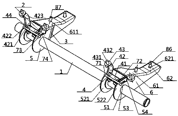
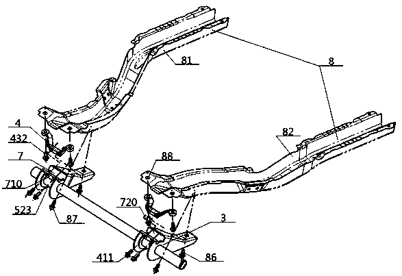
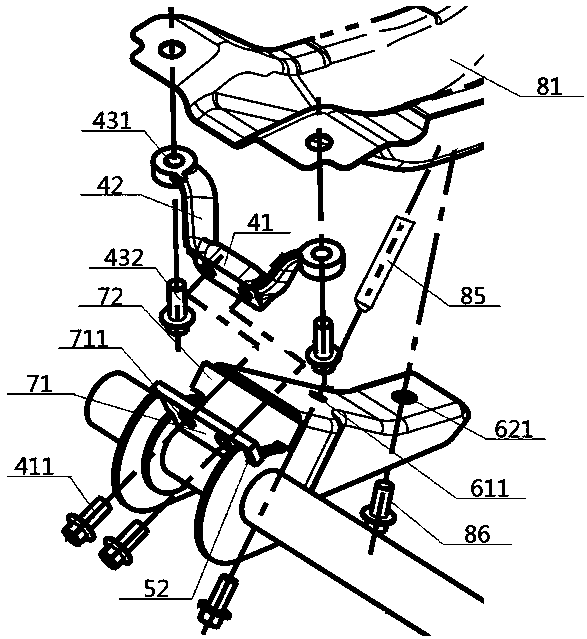
[0049] see figure 1 — Figure 5 , an overturn bracket assembly structure, including an overturn shaft 1 and overturn brackets 2 respectively sheathed at both ends thereof; part 5 and the inner connection part 6, the middle part of the outer connection part 5 is provided with a shaft passing hole 51 for the turning shaft 1 to pass through, and the right side part of the outer connection part 5 is connected to the left side part of the inner connection part 6 connection, the top surface of the inner connection part 6 is connected with the cab 8, and the top of the outer connection part 5 is provided with a concave snap-in mechanism 7, the snap-fit ​​mechanism 7 includes a No. 1 slope 710 and a No. 2 slope 720. The distance between the top of the slope 710 and the second slope 720 is greater than the distance between the bottom; the upper connector 4 includes connecting the middle plate 41 and connecting wing plates 42 connected to its two ends, the middle part of the connection...

Embodiment 2

[0052] Basic content is the same as embodiment 1, the difference is:

[0053] The No. 1 slope 710 is the No. 1 slope 71, and the No. 2 slope 720 is the No. 2 slope 72. The bottom ends of the No. 1 slope 71 and the No. 2 slope 72 are connected to the top of the external connection part 5. The top of the slanted plate 71 extends upwards towards the direction away from the internal connection portion 6, the top end of the second slanted plate 72 extends upwards towards the direction close to the internal connection portion 6, and the distance between the tops of the first slanted plate 71 and the second slanted plate 72 is Greater than the distance between the bottoms, the included angles 73 between the bottoms of the No. 1 slanted plate 71 and the No. 2 slanted plate 72 and the horizontal plane are all acute angles. Preferably, a space 74 between the bottoms of the No. 1 slanted plate 71 and the bottoms of the No. 2 slanted plate 72 is interposed.

Embodiment 3

[0055] Basic content is the same as embodiment 1, the difference is:

[0056] The connection between the upper connector 4 and the bottom 81 of the No. 1 chamber and the bottom 82 of the No. 2 chamber refers to the interconnection of the wing connecting holes 431 and the wing connecting bolts 432;

[0057] The falling of the cab unit to the external connection part 5 means: the bottom 81 of the first room and the bottom 82 of the second room are provided with a room positioning pin hole 83 and a room fixing hole 84, and the top surface of the inner connection part 6 is provided with a bottom Locating pin hole 611 and following fixed connection hole 621, during operation, insert an end that has locating pin 85 in chamber locating pin hole 83 earlier, insert the other end of locating pin 85 down locating pin hole 611 when falling again, to complete whereabouts;

[0058]The fixed connection between the upper connecting piece 4 and the corresponding clamping mechanism 7 refers to...


PUM


Abstract

The utility model discloses a turnover support assembly structure. The turnover support assembly structure comprises a lower overturning piece and an upper connecting piece. The lower overturning piece comprises an outer connecting part and an inner connecting part; a shaft passing hole for the turnover shaft to pass through is formed in the middle of the outer connecting part; the right side partof the outer connecting part is connected with the left side part of the inner connecting part; the top surface of the inner connecting part is connected with a cab; a concave clamping mechanism is arranged at the top of the outer connecting part; the clamping mechanism comprises a first inclined surface and a second inclined surface; the upper connecting piece comprises a connecting middle plateand connecting wing plates connected with the two ends of the connecting middle plate, the middle of the connecting middle plate is connected with the first inclined face, the ends of the connectingmiddle plate are connected with the bottom ends of the connecting wing plates, and the top ends of the connecting wing plates extend upwards and are provided with wing connecting holes connected witha cab. According to the turnover support assembly structure, a connecting bolt is easily tightened at the cab falling and overturning support assembly, and the assembling efficiency is high.

Description

technical field [0001] The invention relates to an overturn bracket connected with a driver's cab, belongs to the technical field of overturn bracket assembly for light commercial vehicles, and in particular relates to an overturn bracket assembly structure and an assembly method thereof. Background technique [0002] In the current technology, the connection method between the flip bracket assembly and the cab is generally to set two fixed points on the front beam, and to set three fixed points on the left and right longitudinal beams respectively. However, due to changes in the driving structure, the There is no fixed point, all fixed points can only be arranged on the left and right longitudinal beams, which squeezes the assembly space, and because the connecting bolts can only be tightened from bottom to top, but due to the blocking of the front suspension bracket assembly, the bracket is flipped The multiple connecting bolts on the assembly cannot be tightened with an a...

Claims


Application Information

Patent Timeline
Patent Type & Authority Applications(China)
IPC IPC(8): B62D33/067B62D65/02
CPCB62D33/067B62D65/02
Inventor 姜轶帆陈竹君王莉张新宇赵雅倩姚缙然张健慧
Owner DONGFENG AUTOMOBILE COMPANY
Learn More