Blood plasma bag storage device for blood department

A storage device and plasma bag technology, which is applied in the field of blood plasma bag storage devices, can solve the problems of storage devices such as fixation, damage, and poor pressure resistance, and achieve the effects of easy removal and cleaning, stable device structure, and convenient use

Active Publication Date: 2020-08-18
SHENZHEN CHILDRENS HOSPITAL
View PDF14 Cites 0 Cited by
  • Summary
  • Abstract
  • Description
  • Claims
  • Application Information

AI Technical Summary

Problems solved by technology

[0003] The existing blood plasma bag storage device has a single structure and function. Generally, the plasma is only placed inside the storage device with a cooling effect, and the storage device cannot be fixed. The structure is not stable enoug

Method used


Image

  • Blood plasma bag storage device for blood department
  • Blood plasma bag storage device for blood department
  • Blood plasma bag storage device for blood department

Examples


Embodiment 1

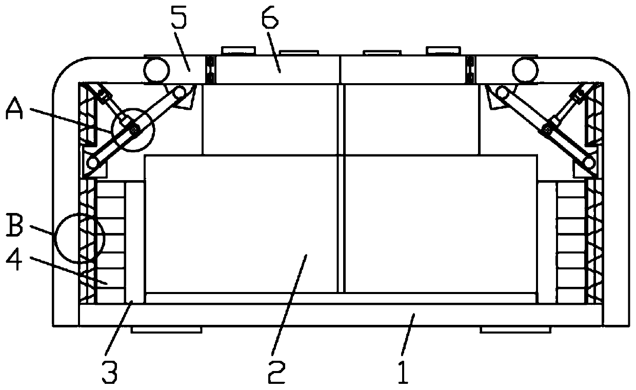
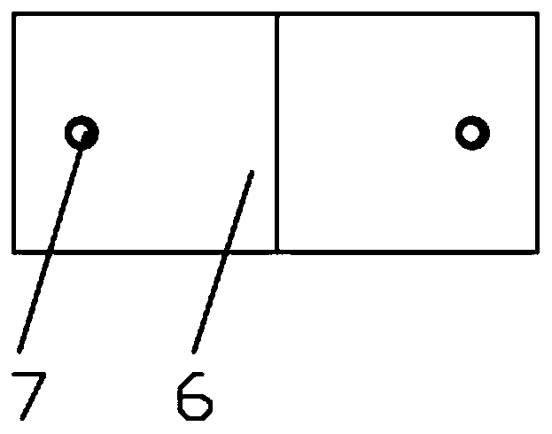
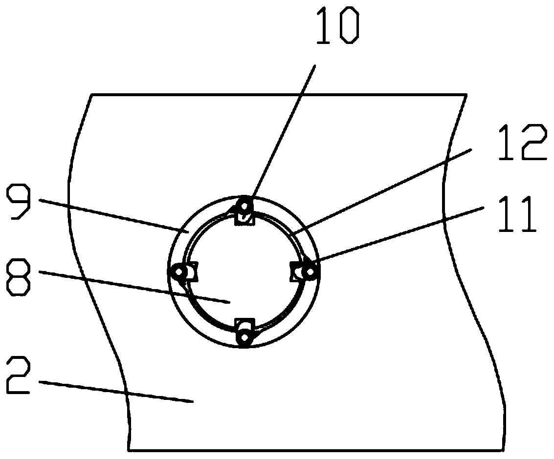
[0024] A blood plasma bag storage device, comprising an outer box body 1, a storage box 2 is arranged inside the outer box body 1, an upper side door 6 is hinged on the upper surface of the outer box body 1, and a horizontal plate is hinged on the side wall of the upper side door 6 5. The horizontal plate 5 is hinged with the outer box body 1, and the inside of the storage box 2 is installed with a mounting seat 9, and the inside of the mounting seat 9 is provided with a mounting groove 12, and the inside of the mounting groove 12 is equipped with a positioning seat 8, and the side of the positioning seat 8 The wall is provided with a locking groove 11, and the inside of the locking groove 11 is plugged with a locking lever 10. One end of the locking lever 10 is rotationally connected with the mounting base 9, and a torsion spring is installed between the mounting base 9 and the mounting base 9, and the positioning The upper end of the seat 8 is connected with a rotating rod, a...

Embodiment 2

[0027] A blood plasma bag storage device, comprising an outer box body 1, the inner side wall of the outer box body 1 is connected with a rubber snap-in block A17 and a rubber snap-in block B18, and the side wall of the rubber snap-in block B18 is fixedly connected with the cooling tube 4 , the rubber clamping block A17 and the rubber clamping block B18 are set in an inverted trapezoidal structure, the rubber clamping block A17 and the rubber clamping block B18 are clamped with each other, see the attached Figure 5 ; By setting the rubber clamping block A17 and the rubber clamping block B18 which are clamped with each other, the compression resistance of the side wall of the outer box body 1 is increased, and the structure is stable.

[0028] The inside of the outer box body 1 is provided with a storage box 2, the upper surface of the outer box body 1 is hinged with an upper side door 6, the side wall of the upper side door 6 is hinged with a horizontal plate 5, the horizontal...


PUM


Abstract

The invention discloses a blood plasma bag storage device for a blood department. The storage device comprises an outer box body, wherein a storage box is arranged in the outer box body, upper side doors are hinged to the upper surface of the outer box body, transverse plates are hinged to the side walls of the upper side doors, the transverse plates are hinged to the outer box body, mounting seats are mounted in the storage box, a mounting groove is formed in each mounting seat, and a positioning seat is mounted in each mounting groove; inclined rods A and inclined rods B are arranged at thetop positions of the interior of the outer box body, one ends of each inclined rod A and each inclined rod B are rotatably connected and connected with an middle piece, one end of each middle piece isconnected with a telescopic rod, the bottom of the inner side wall of the outer box body is connected with a refrigeration cylinder, and a heat dissipation cylinder is arranged on the surface of therefrigeration cylinder; and a locking groove is formed in the side wall of each positioning seat, and a locking rod is inserted into each locking groove. The device is stable in structure, convenientto transport, convenient to use, good in pressure resistance and reasonable in design.

Description

technical field [0001] The invention relates to the technical field of blood plasma storage, in particular to a blood plasma bag storage device. Background technique [0002] The Department of Hematology treats acute and chronic leukemia, malignant lymphoma, multiple myeloma and other malignant blood diseases, as well as common blood diseases such as aplastic anemia and idiopathic thrombocytopenic purpura. Plasma is essential when patients need emergency treatment Rarely, the plasma needs to be stored in a hematology plasma bag storage device before use. [0003] The existing blood plasma bag storage device has a single structure and function. Generally, the plasma is only placed inside the storage device with a cooling effect, and the storage device cannot be fixed. The structure is not stable enough, and it is inconvenient to use, and the storage device is generally a box Body structure, poor pressure resistance, when multiple storage devices are stacked, it will generate...

Claims


Application Information

Patent Timeline
IPC IPC(8): B65D25/02B65D43/16B65D43/22B65D81/18B65D51/24
CPCB65D25/02B65D43/164B65D43/22B65D51/24B65D81/18
Inventor 刘四喜文飞球杨艳澜王春静周小辉
Owner SHENZHEN CHILDRENS HOSPITAL
Why Eureka
Try Eureka