A construction method of anti-collapse pouring formwork for diaphragm walls suitable for soft soil areas

A construction method and technology of underground diaphragm wall, applied in construction, sheet pile wall, foundation structure engineering, etc., can solve the problems such as difficult control of wall flatness, easy collapse of ground connection wall groove wall, difficult quality assurance, etc., to achieve guaranteed The quality of concrete pouring, the significance of promotion, and the effect of preventing the wall from collapsing

Active Publication Date: 2021-07-20
CHINA STATE CONSTRUCTION ENGINEERING CORPORATION +1
View PDF8 Cites 0 Cited by
  • Summary
  • Abstract
  • Description
  • Claims
  • Application Information

AI Technical Summary

Problems solved by technology

[0014] The purpose of the present invention is to provide a construction method of diaphragm wall anti-collapse pouring formwork suitable for soft soil areas, so as to solve the difficulty in ensuring the quality of the diaphragm wall in the prior art in the underwater pouring construction and the flatness of the wall surface in weak strata. Difficult to control, the steel cage floats up, the pipe enters the mud when the concrete is poured, and the groove wall of the ground connection wall in the soft soil area is easy to collapse

Method used


Image

  • A construction method of anti-collapse pouring formwork for diaphragm walls suitable for soft soil areas
  • A construction method of anti-collapse pouring formwork for diaphragm walls suitable for soft soil areas
  • A construction method of anti-collapse pouring formwork for diaphragm walls suitable for soft soil areas

Examples


Embodiment Construction

[0054]In order to make the technical means, innovative features, goals and effects achieved by the present invention easy to understand, the present invention will be further described below.

[0055] The examples described here are specific specific implementations of the present invention, and are used to illustrate the concept of the present invention. They are all explanatory and exemplary, and should not be construed as limiting the implementation of the present invention and the scope of the present invention. In addition to the embodiments described here, those skilled in the art can also adopt other obvious technical solutions based on the claims of the application and the contents disclosed in the description, and these technical solutions include adopting any obvious changes made to the embodiments described here. Replacement and modified technical solutions.

[0056] In the description of the present invention, it should be noted that the terms "upper", "lower", "in...


PUM


Abstract

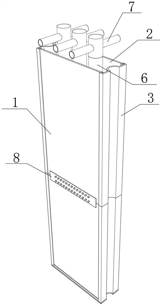
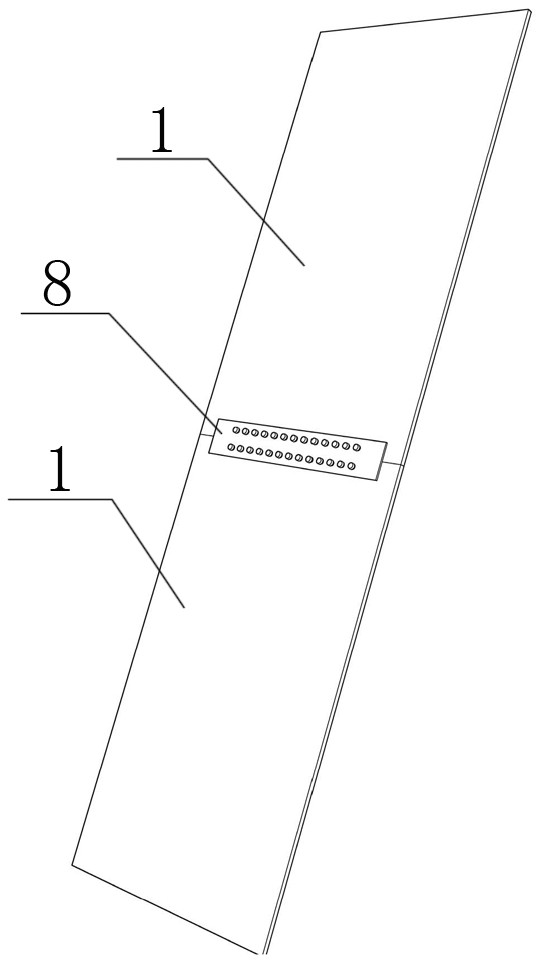
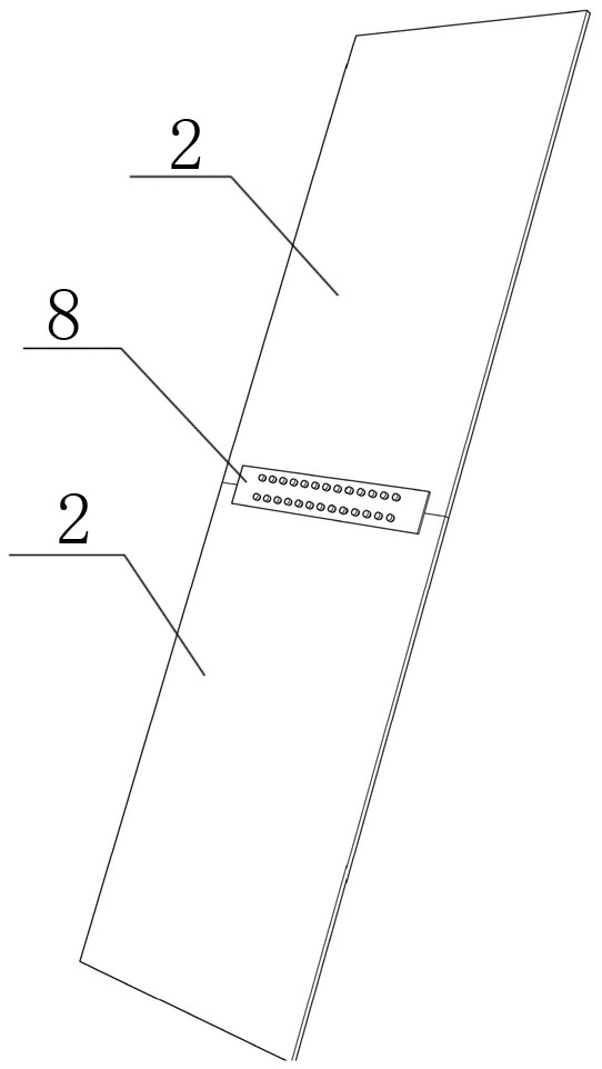
The construction method of the diaphragm wall anti-collapse pouring formwork suitable for soft soil areas of the present invention belongs to the technical field of underground diaphragm wall construction, and includes a soil-facing side support plate, a back-soil side support plate, an end plate, a bottom support plate and The mud discharge pipe, the side support plate facing the soil, the side support plate behind the soil, the end plate and the bottom support plate form a box-shaped structure with an open top, and the bottom support plate is provided with a mud discharge hole. The bottom of the pipe is inserted into the mud discharge hole, and the top of the mud discharge pipe exceeds the top of the soil-facing side support plate and the back-soil side support plate and extends to the outside of the underground diaphragm wall groove section. The formwork can effectively prevent wall mud from entering the formwork, ensure that the underground continuous wall is poured in an anhydrous environment, and prevent mud from being trapped during concrete pouring. When the reinforcement cage is lowered, it will not float up due to being lifted by the mud, which ensures the quality of concrete pouring. When pouring the concrete of the underground diaphragm wall, there is no need to insert the conduit in advance, and the concrete will not disturb the groove wall, which can effectively prevent the groove wall from collapsing in soft soil areas.

Description

technical field [0001] The invention relates to the technical field of underground diaphragm wall construction, in particular to a construction method for a diaphragm wall anti-collapse pouring formwork suitable for soft soil areas. Background technique [0002] With the rapid development of the economy and the continuous improvement of the level of urbanization, the development of underground space is also increasing. The open cut method is the most commonly used construction method, and the underground diaphragm wall is one of the most commonly used foundation pit enclosure structures in the open cut method. one. [0003] However, at present, most of the underground diaphragm walls are constructed by on-site underwater pouring. When pouring concrete, it is necessary to continuously inject mud into the groove section, and there are the following problems: [0004] 1. It is not easy to guarantee the quality during pouring [0005] When the ground connection wall is poured ...

Claims


Application Information

Patent Timeline
Patent Type & Authority Patents(China)
IPC IPC(8): E02D5/20E02D15/02
CPCE02D5/20E02D15/02
Inventor 郭建涛油新华段苒
Owner CHINA STATE CONSTRUCTION ENGINEERING CORPORATION
Why Eureka
Try Eureka