
Air inlet mechanism used for piston compressor

A compressor and piston type technology, which is applied to the field of air intake mechanism for piston compressors, can solve the problems of reduced air intake speed, inability to meet the normal use of piston compressors, and low air compression of piston compressors, etc. Achieve the effect of preventing excessive temperature, improving heat dissipation and uniform air intake

Active Publication Date: 2020-08-18
浙江神冈机械有限公司
View PDF17 Cites 4 Cited by
  • Summary
  • Abstract
  • Description
  • Claims
  • Application Information

AI Technical Summary

Problems solved by technology

[0004] The above-mentioned patents also have the following disadvantages: the main reason for the air intake of the piston compressor is that the internal pressure decreases and the pressure difference is generated, but the above-mentioned device uses the air inlet to block the impurities of large particles from entering the device. Internally, the air intake speed of the device is reduced, which may cause the piston compressor to compress less air, which cannot meet the normal use of the piston compressor

Method used


Image

  • Air inlet mechanism used for piston compressor
  • Air inlet mechanism used for piston compressor
  • Air inlet mechanism used for piston compressor

Examples


Embodiment 1

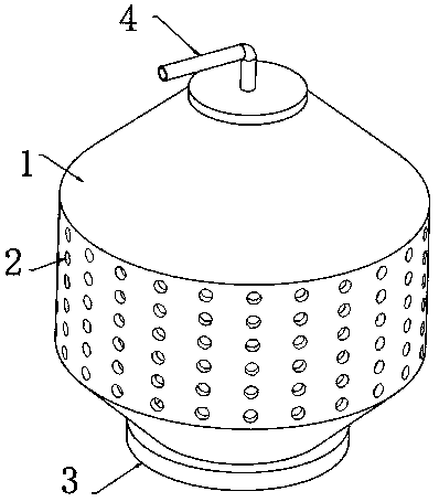
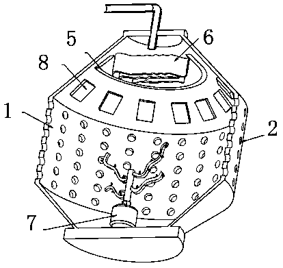
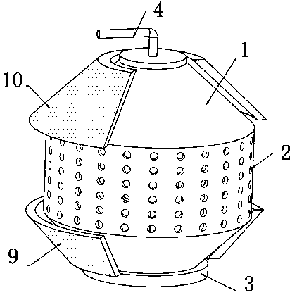
[0030] refer to Figure 1-4 , an air intake mechanism for a piston compressor, comprising an air intake box 1, the top outer wall of the air intake box 1 is connected with an air guide pipe 4 through a flange, and one side outer wall of the air intake box 1 is provided with equidistantly distributed air inlets 2 , the air inlet box 1 is a structure with two small ends and a large middle, the diameter of the air inlet 2 is between 3-6mm, and the air inlet 2 is located in the middle of the air inlet box 1, and the inner wall of one side of the air inlet box 1 is fixed by screws. The semiconductor refrigeration sheet 8, and the bottom inner wall of the air inlet box 1 is fixed with a motor 7 by screws, the output shaft of the motor 7 is connected with a rotating rod 12 through a coupling, and the outer wall of the rotating rod 12 is welded with irregularly distributed stirring rods 13, The stirring rod 13 has a wavy structure, and the wave shapes of the stirring rods 13 are diffe...

Embodiment 2

[0036] refer to Figure 5 , an air intake mechanism for a piston compressor. Compared with Embodiment 1, this embodiment also includes a second baffle 14 that is equidistantly fixed to the outer wall of one side of the first baffle 6 by screws. The second baffle The flow plate 14 is a zigzag structure.

[0037]Connect the device to the power supply, turn on the semiconductor cooling plate 8 to reduce the temperature value inside the air inlet box 1, resulting in a decrease in pressure, which can accelerate the speed of air flowing into the air inlet box 1, and increase the air intake in the same time, turn on the motor 7, and the motor 7 drives the rotation The rod 12 rotates, and the stirring rod 13 is a wavy structure with different shapes, which can generate vortices of different shapes. Mixing effect, cold air can cool down the interior of the piston compressor, effectively preventing the internal temperature of the piston compressor from being too high, the first dusty l...


PUM


Abstract

The invention belongs to the technical field of air inlet mechanisms, and particularly relates to an air inlet mechanism used for a piston compressor. By aiming at the problem of a small air inlet quantity, the invention now puts forward the following scheme that the air inlet mechanism comprises an air inlet box, wherein the outer wall of the top of the air inlet box is connected with an air guiding pipe through a flange; the outer wall of one side of the air inlet box is provided with air inlets which are distributed at equal distances; the air inlet box is of a structure of which two ends are small and the middle is big; the diameter of each air inlet is 3-6 mm; and the air inlets are positioned in the middle of the air inlet box. The air inlet mechanism is provided with semiconductor refrigeration sheets, a motor, a rotary rod, stirring rods and connecting rods, when the semiconductor refrigeration sheets are started, a temperature value in the air inlet box can be lowered, pressure intensity is caused to be lowered to accelerate speed for air to flow into the air inlet box, and the air inlet quantity is increased in equal time. A motor is started, the motor drives the rotary rod to rotate, the stirring rods are of wave-shaped structures with different shapes, vortexes of different shapes can be generated, and cold air generated by the semiconductor refrigeration sheets canbe mixed.

Description

technical field [0001] The invention relates to the technical field of air intake mechanisms, in particular to an air intake mechanism for a piston compressor. Background technique [0002] A piston compressor is a compressor that relies on the reciprocating motion of a piston to pressurize and transport gas. It is mainly composed of working chamber, transmission parts, fuselage and auxiliary parts. The working chamber is directly used to compress the gas, and is composed of a cylinder, a cylinder liner, an air valve, a packing, a piston and a piston rod. [0003] After searching, the Chinese patent authorization number is CN109899852A, which discloses an air inlet device, which includes a casing, an impeller rotatably arranged on the casing, and a display stand. [0004] The above-mentioned patents also have the following disadvantages: the main reason for the air intake of the piston compressor is that the internal pressure decreases and the pressure difference is genera...

Claims


Application Information

Patent Timeline
Patent Type & Authority Applications(China)
IPC IPC(8): F04B39/00F04B39/06F04B39/16F25B21/02B01F7/18
CPCF04B39/00F04B39/06F04B39/16F25B21/02F25B2321/0251B01F27/90
Inventor 何学峰
Owner 浙江神冈机械有限公司
Learn More