
Aero-engine turbine blade sampling clamp

A technology for aero-engine and turbine blades, applied in the field of life design and aero-engine strength, can solve the problems of poor clamping and positioning operability of the fixture, poor applicability of the leading edge, and reduced sampling accuracy, so as to achieve sampling standardization and Consistency, high sampling and positioning accuracy, and strong engineering applicability

Pending Publication Date: 2020-08-18
AECC SHENYANG ENGINE RES INST
View PDF6 Cites 6 Cited by
  • Summary
  • Abstract
  • Description
  • Claims
  • Application Information

AI Technical Summary

Problems solved by technology

[0003] However, the difficulty of real blade sampling technology is that the structure of turbine blades is very complex, mostly hollow blades, curved and twisted, and contain special structures such as air film holes, baffles, spoiler columns, etc., and the sampling samples themselves are small-sized non-standard parts , the test dispersion is large, which leads to at least the following problems in some existing sampling fixtures:
[0004] 1) The existing sampling fixture is only suitable for the relatively flat sampling position, and the sampling position has relatively large limitations, such as poor applicability at the leading edge where the life of the blade is more severely damaged;
[0005] 2) The clamping part of the existing sampling fixture cannot be fixed, resulting in the inability to guarantee the positioning consistency of the sampling position in the follow-up;
[0006] 3) The existing sampling fixture has fewer positioning surfaces, and the clamping and positioning operability of the fixture during sampling is poor, resulting in a decrease in sampling accuracy

Method used


Image

  • Aero-engine turbine blade sampling clamp
  • Aero-engine turbine blade sampling clamp
  • Aero-engine turbine blade sampling clamp

Examples


Embodiment Construction

[0027] In order to make the purpose, technical solution and advantages of the application more clear, the technical solution in the embodiment of the application will be described in more detail below in conjunction with the drawings in the embodiment of the application. In the drawings, the same or similar reference numerals denote the same or similar elements or elements having the same or similar functions throughout. The described embodiments are some, but not all, embodiments of the application. The embodiments described below by referring to the figures are exemplary, and are intended to explain the present application, and should not be construed as limiting the present application. Based on the embodiments in this application, all other embodiments obtained by persons of ordinary skill in the art without creative efforts fall within the protection scope of this application. Embodiments of the present application will be described in detail below in conjunction with th...


PUM


Abstract

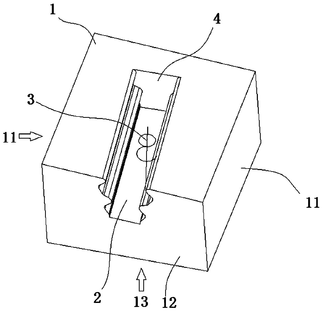
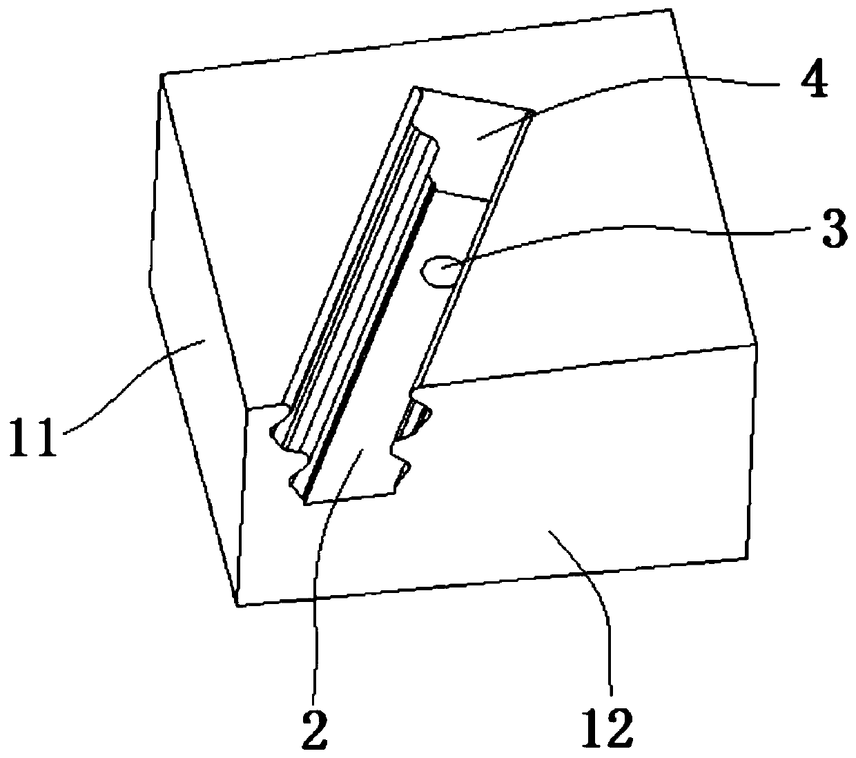
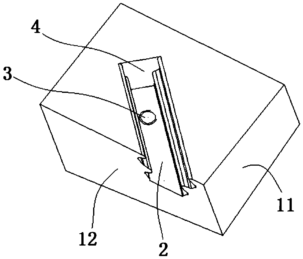
The invention belongs to the technical field of aero-engine strength and service life design, and especially relates to an aero-engine turbine blade sampling clamp. The clamp is used for clamping a turbine blade with a preset sampling position and comprises a hexahedron-shaped body part, a mortise is formed in the top face of the body part in a sunken mode, a bolt hole for fixing is formed in thebottom of the body part, and the bolt hole for fixing perpendicularly penetrates into the mortise from the bottom face of the body part from bottom to top. According to the aero-engine turbine blade sampling clamp disclosed by the invention, the sampling of the turbine blade can be realized. The blade is clamped and fixed, the sampling position space angle is adjusted, a plurality of effective positioning faces are provided for cutting machining, standardization and consistency of sampling are guaranteed, then effectiveness and precision of obtained real blade mechanical property test result data are guaranteed, and the clamp can be applied to turbine blade real component performance obtaining and blade strength and service life design.

Description

technical field [0001] The application belongs to the technical field of aero-engine strength and life design, and in particular relates to an aero-engine turbine blade sampling fixture. Background technique [0002] Material properties are the basis of structural strength design of aero-engines and one of the important inputs to ensure the accuracy of strength design. It is well known that there are differences between the performance of real components of turbine blades and the performance of standard parts, especially turbine blades, which have complex structures and adopt advanced high-temperature components such as orientation and single crystal. Alloy materials. Therefore, the mechanical performance test of the test piece obtained from the actual turbine blade can truly reflect the actual situation of the blade's mechanical performance, surface finish, crystal orientation, thin-wall effect, etc., and obtain real and reliable test data to support the engine strength. d...

Claims


Application Information

Patent Timeline
IPC IPC(8): G01N1/04
CPCG01N1/04
Inventor 王威耿瑞赵娜葛长闯曹航从佩红
Owner AECC SHENYANG ENGINE RES INST
Learn More