Sampling circuit for electromagnetic heating product

A technology of sampling circuit and power circuit, which is applied in the electronic field, can solve the problems of high manufacturing cost, complex circuit, easy to generate parasitic inductance, etc., and achieve the effect of improving production and use efficiency, strong anti-interference ability, and ensuring consistency

Pending Publication Date: 2020-08-18
GUANGDONG REAL DESIGN INTELLIGENT TECH
View PDF0 Cites 0 Cited by
  • Summary
  • Abstract
  • Description
  • Claims
  • Application Information

AI Technical Summary

Problems solved by technology

The work of the induction cooker itself has an electromagnetic conversion process, so the current sampling signal is easily disturbed, resulting in power fluctuations
[0003] In the existing technology, in the working circuit of electromagnetic heating products, the rectification circuit is generally used to convert the alternating current into direct current to supply power to the load. It is necessary to detect the current in the load circuit to control the heating power state. At present, the common technology in the industry uses discrete resistors for current sampling. Then the discrete operational amplifier is used to amplify the signal proportionally and output it to the AD port of the chip, convert the analog signal into a digital signal, and control the power of electromagnetic heating through the program algorithm. There are problems in this method: the circuit is complicated, the PCB wiring requirements are high, and it is easy to generate parasitic Inductance and parasitic capacitance lead to poor consistency of sampling signals; there are many peripheral devices, which require additional calibration processes in production, and the cost of materials and manufacturing is high; devices are easily affected by the environment, oxidation, dust pollution, failure, sampling signal changes, and quality is difficult to guarantee

Method used


Image

  • Sampling circuit for electromagnetic heating product
  • Sampling circuit for electromagnetic heating product
  • Sampling circuit for electromagnetic heating product

Examples


Embodiment Construction

[0021] A sampling circuit for electromagnetic heating products of the present invention will be described with reference to the accompanying drawings.

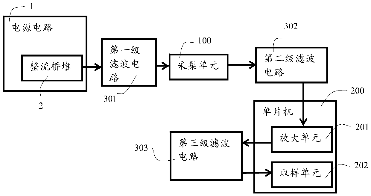
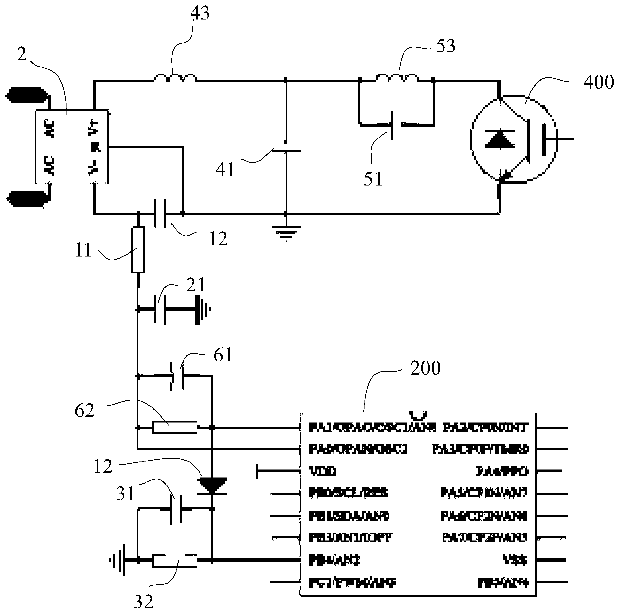
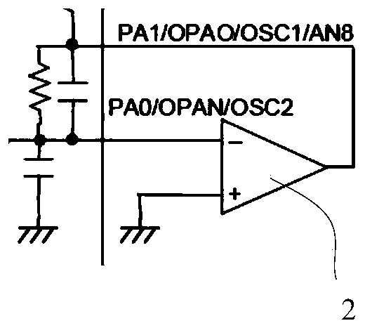
[0022] Such as Figure 1 to Figure 2 As shown, a sampling circuit for electromagnetic heating products includes a power supply circuit 1 for providing a DC output by using a rectifier bridge stack 2, and also includes a collection unit 100 connected to the power supply circuit 1, and The acquisition unit 100 outputs sampling signals; the single-chip microcomputer 200, the single-chip 200 integrates an amplifying unit 201, the amplifying unit 201 is connected to the acquisition unit 100, the amplifying unit 201 amplifies the output signal of the acquisition unit 100, and the The amplifying unit 201 includes an inverting amplifier; a sampling unit 202, the sampling unit 202 is connected to the amplifying unit 201, the sampling unit 202 performs sampling processing on the acquisition unit 100; a filtering unit, the filtering unit in...


PUM


Abstract

The invention discloses a sampling circuit for an electromagnetic heating product, which comprises a power supply circuit for providing direct current output by using a bridge rectifier, an acquisition unit, a single chip microcomputer, a sampling unit and a filtering unit; the acquisition unit is connected with the power supply circuit and outputs a sampling signal; an amplification unit is integrated in the single chip microcomputer, the amplification unit is connected with an acquisition unit, the amplification unit amplifies an output signal of the acquisition unit, and the amplification unit is an inverting amplifier; the sampling unit is connected with the amplifying unit, and the sampling unit is used for sampling the collecting unit; the filtering unit comprises a first-stage filtering circuit, a second-stage filtering circuit and a third-stage filtering circuit. The invention aims to provide the sampling circuit for the electromagnetic heating product, a calibration process iscanceled, and the use of a large number of components is relatively saved, so that the structure of the sampling circuit is simplified, and the production efficiency of the product is improved.

Description

Technical field [0001] The invention relates to the field of electronic technology, in particular to a sampling circuit for electromagnetic heating products. Background technique [0002] As a new type of kitchen heating appliance, induction cooker has the characteristics of high efficiency and energy saving, which is deeply loved by consumers. The stability of heating power is the focus of consumers' attention, and the realization of power adjustment is based on the sampling value of current To decide, so whether the power is stable depends on the stability of the current sampling signal. The work of the induction cooker itself has an electromagnetic conversion process, so the current sampling signal is easy to be disturbed, causing power fluctuations. [0003] In the prior art, in the working circuit of electromagnetic heating products, AC power is generally converted to DC power to supply power to the load through a rectifier circuit. The current in the load loop needs to be de...

Claims


Application Information

Patent Timeline
Patent Type & Authority Applications(China)
IPC IPC(8): G01R19/25
CPCG01R19/25
Inventor 汪军方桦陈泽龙
Owner GUANGDONG REAL DESIGN INTELLIGENT TECH
Why Eureka
Try Eureka