Eureka AIR delivers breakthrough ideas for toughest innovation challenges, trusted by R&D personnel around the world.

Direct-current charger detection system and method

A detection system and charger technology, applied in the direction of measuring electricity, measuring devices, measuring electrical variables, etc., can solve the problems of large influence of human factors, long time consumption, affecting detection efficiency, etc., to improve safety and accuracy, save money Manpower and cost, the effect of improving detection efficiency

Pending Publication Date: 2020-08-18
NORTH CHINA GRID MEASUREMENT CENT +3
View PDF0 Cites 5 Cited by
  • Summary
  • Abstract
  • Description
  • Claims
  • Application Information

AI Technical Summary

Problems solved by technology

[0003] The traditional detection method of charging facilities requires many and complex types of external devices, requires manual wiring, and takes a long time, resulting in low detection efficiency and prone to miswiring, resulting in personal injury and equipment damage
During the interoperability test, it is necessary to use an oscilloscope to manually capture the waveform of each test, which has poor stability and is greatly affected by human factors, so it is not suitable for on-site testing; during the communication protocol consistency test, an external CAN box is required to read the message. And there is no message translation function, and the messages must be translated one by one according to the standard, which seriously affects the detection efficiency

Method used


Image

  • Direct-current charger detection system and method
  • Direct-current charger detection system and method
  • Direct-current charger detection system and method

Examples


Embodiment Construction

[0023] The implementation of the present invention will be described in detail below in conjunction with the accompanying drawings and examples, so as to fully understand and implement the process of how to apply technical means to solve technical problems and achieve technical effects in the present invention. It should be noted that, as long as there is no conflict, each embodiment and each feature of each embodiment in the present invention can be combined with each other, and the formed technical solutions are all within the protection scope of the present invention.

[0024] In the description of this specification, the words "comprising", "comprising", "having", "containing" and so on are all open terms, meaning including but not limited to. A description referring to the terms "one embodiment," "a particular embodiment," "some embodiments," "for example," etc., means that a particular feature, structure, or characteristic described in connection with the embodiment or ex...


PUM


Abstract

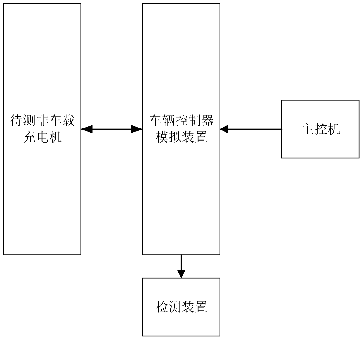
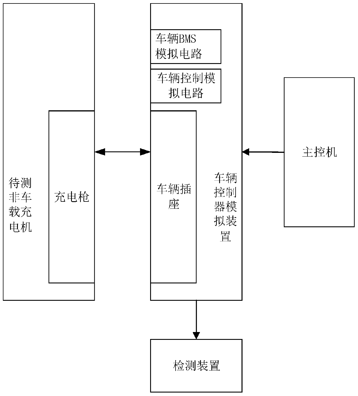
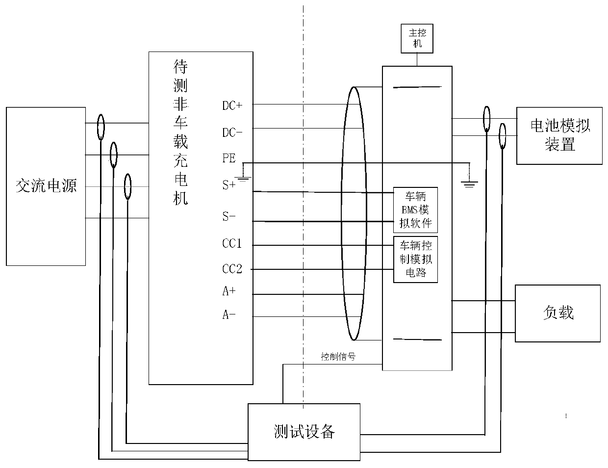
The invention discloses a DC charger detection system and method, and the system comprises a vehicle controller simulation device which simulates a vehicle BMS control system, and builds the message data interaction with a to-be-detected off-board charger through a CAN line in a charging gun; a vehicle fault state is simulated through each contact on the vehicle socket according to the received control instruction; a detection device acquires communication message data between the vehicle controller simulation device and the to-be-detected off-board charger, translates the message data into apredetermined format, analyzes the communication protocol consistency between the vehicle controller simulation device and the to-be-detected off-board charger according to a preset rule, acquires a communication protocol consistency analysis result and stores the communication protocol consistency analysis result; the waveform detection signals of all contacts and contactor signals or a front-endvoltage of the non-vehicle-mounted charger to be detected in the simulated vehicle fault state of all the contacts are collected, and an interoperation test detection result of the non-vehicle-mounted charger to be detected is obtained through a comparison result of a difference value between the waveform detection signal and the contactor signal or the front end voltage and a preset threshold value; and a main control computer outputs a control instruction.

Description

technical field [0001] The invention relates to the field of vehicle charging equipment detection, in particular to a DC charger detection system and method. Background technique [0002] Driven by relevant national policies, new energy electric vehicles are widely popularized, and the number of supporting basic charging facilities has also achieved rapid growth. In the process, many problems of poor charging compatibility and safety were highlighted, which put forward higher requirements for strict inspection quality. In addition, electric vehicle charging stations also need regular testing, which puts forward more urgent requirements for improving the automation level of testing equipment and the work efficiency of testing personnel. [0003] The traditional detection method of charging facilities requires many types of external devices and is complex, requiring manual wiring, which takes a long time, resulting in low detection efficiency and prone to miswiring, resulting...

Claims


Application Information

Patent Timeline
Patent Type & Authority Applications(China)
IPC IPC(8): G01R31/00
CPCG01R31/00
Inventor 姜振宇赵思翔韩迪王亚超易忠林刘科学谭志强袁瑞铭刘晓天刘影刘晶巨汉基庞富宽郭皎李文文王杰钟侃王晨崔文武汪洋高帅
Owner NORTH CHINA GRID MEASUREMENT CENT
Why Eureka
Eureka Blog
Learn More