Power cabinet capable of automatically adjusting heat dissipation

An automatic adjustment and power cabinet technology, applied in the direction of circuits, electric switches, electrical components, etc., can solve the problem that the power cabinet in the community does not have the ability to protect objects from high altitudes, increase the internal temperature of the power cabinet, and drop to the top of the power cabinet, etc. problem, to achieve the effect of accelerating the mixing exchange efficiency, strengthening the protection effect, and facilitating heat dissipation

Inactive Publication Date: 2020-08-18
李贺龙
View PDF5 Cites 15 Cited by
  • Summary
  • Abstract
  • Description
  • Claims
  • Application Information

AI Technical Summary

Problems solved by technology

[0005] Aiming at the deficiencies of the prior art, the present invention provides a power cabinet with automatic heat dissipation adjustment, which has the advantages of simple structure, improved heat dissipation efficiency of the cabinet body and automatic opening of the working switch of the fan, etc. The general design of the cabinet is relatively simple, and there are the following defects in use. First, the community power cabinet of the prior art does not have the ability to protect objects from falling from high altitudes, and cannot buffer objects that are accidentally dropped. The top of the cabinet causes damage to the power cabinet. Secondly, the power cabinet of the residential area in the prior art generally dissipates heat by installing a fan, but the fan is always in a working state. The existing technology cannot self-adjust the working state according to the temperature inside the power cabinet. Keeping the fan in the working state for a long time not only wastes electricity, but also increases the temperature inside the power cabinet when the fan works for a long time

Method used


Image

  • Power cabinet capable of automatically adjusting heat dissipation
  • Power cabinet capable of automatically adjusting heat dissipation
  • Power cabinet capable of automatically adjusting heat dissipation

Examples


Embodiment Construction

[0031] The following will clearly and completely describe the technical solutions in the embodiments of the present invention with reference to the accompanying drawings in the embodiments of the present invention. Obviously, the described embodiments are only some, not all, embodiments of the present invention. Based on the embodiments of the present invention, all other embodiments obtained by persons of ordinary skill in the art without making creative efforts belong to the protection scope of the present invention.

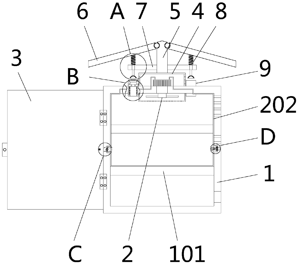
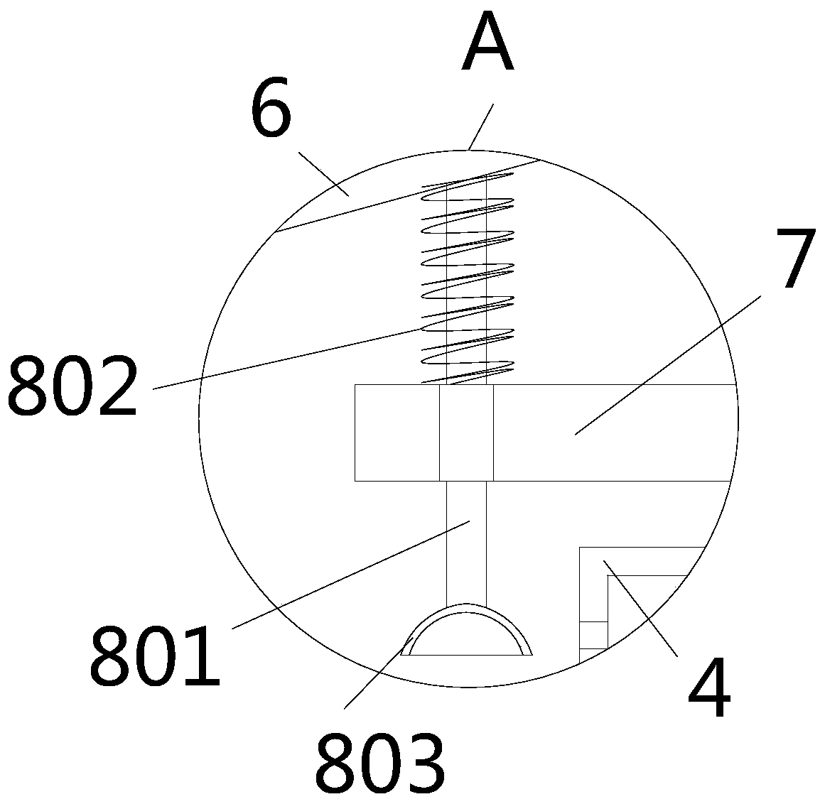
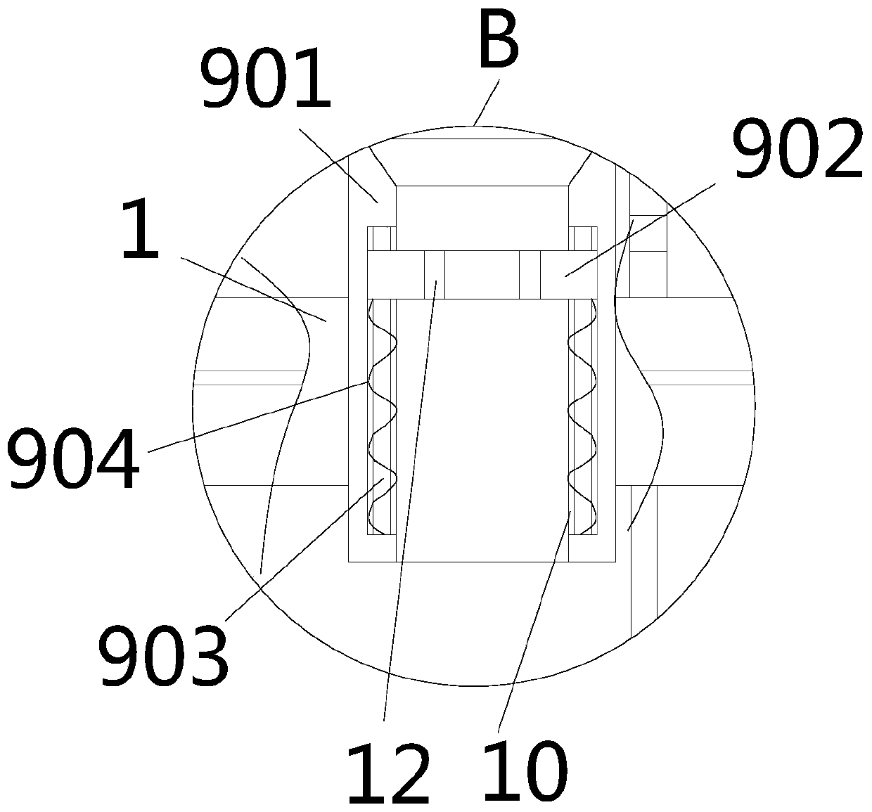
[0032] see Figure 1-7, the present invention provides a technical solution: a power cabinet with automatic heat dissipation adjustment, including a cabinet body 1, a fan 2 and a cabinet door 3, the cabinet door 3 is movably installed on the left side wall of the cabinet body 1 through a hinge, and the fan 2 is arranged on the On the cabinet body 1, two horizontal plates 101 are fixedly installed horizontally in the cavity of the cabinet body 1, the left and r...


PUM


Abstract

The invention relates to the technical field of power cabinets. The invention discloses a power cabinet capable of automatically adjusting heat dissipation. The cabinet comprises a cabinet body, a fanand a cabinet door; a fixed box is fixedly installed at the top of the cabinet body, a supporting plate is arranged at the top of the fixed box, symmetrical ceiling inclined plates are movably installed on the two sides of the top of the supporting plate through hinges, limiting plates are arranged on the outer walls of the left side and the right side of the supporting plate, and buffer mechanisms are arranged between the two limiting plates and the corresponding ceiling inclined plates. According to the invention, through the arrangement of the air inlet device, the mechanical movement matched with the buffer mechanism is realized; air injection and air compression effects are achieved in the cabinet body cavity; air outside the cabinet body is rapidly injected into the cavity of the cabinet body, so the mixing exchange efficiency of air in the cavity of the cabinet body and outside air is improved, and cooling and heat dissipation of the cabinet body are achieved; meanwhile, the limiting springs can achieve the secondary buffering pressure reduction effect on the buffering rods, the buffering capacity for objects falling from high altitudes is improved, and the protection effect on the cabinet body is enhanced.

Description

technical field [0001] The invention relates to the technical field of power cabinets, in particular to a power cabinet with automatic heat dissipation adjustment. Background technique [0002] With the increasing number of electrical appliances in life, a lot of manual labor is replaced by electronic equipment. The stability of electric power needs to be guaranteed by qualified equipment. The equipment for power control is generally installed in the power cabinet. [0003] However, the general design of the community power cabinets in the prior art is relatively simple, and there are the following defects in use. First, the community power cabinets in the prior art do not have the ability to protect objects from falling from high altitudes, and cannot buffer objects that accidentally fall. Placed objects fall directly on the top of the power cabinet, causing damage to the power cabinet. Secondly, the power cabinets of the existing technology generally use fans to dissipate ...

Claims


Application Information

Patent Timeline
Patent Type & Authority Applications(China)
IPC IPC(8): H02B1/30H02B1/38H02B1/54F16F15/04H02B1/56H02B1/24H01H29/30
CPCF16F15/04H01H29/30H02B1/24H02B1/30H02B1/38H02B1/54H02B1/565
Inventor 李贺龙
Owner 李贺龙
Why Eureka
Try Eureka