a heat sink

A heat sink, cylindrical technology, applied in the direction of cooling/ventilation/heating transformation, electrical components, electrical equipment structural parts, etc. Heat dissipation requirements, convenient connection, and ensure the effect of heat dissipation

Active Publication Date: 2021-04-06
SUZHOU TONGZHUN PRECISION PLASTIC HARDWARE CO LTD +1
View PDF3 Cites 0 Cited by
  • Summary
  • Abstract
  • Description
  • Claims
  • Application Information

AI Technical Summary

Problems solved by technology

[0002] Electronic communication equipment includes some equipment including integrated circuits, transistors and electronic tubes, such as routers and some computer-related equipment. These electronic communication equipment will generate a lot of heat during operation. If the heat is not discharged in time, it will affect electronic communication. For the normal operation of the equipment, it is necessary to carry out timely heat dissipation treatment on the electronic communication equipment. The conventional heat dissipation treatment usually uses a cooling fan. The function of the cooling fan is to speed up the air exchange. However, when the electronic equipment generates more heat, The heat dissipation effect of the cooling fan is difficult to meet the needs, and the heat dissipation effect is poor.
[0003] In addition, the cooling fan is used to dissipate heat from the communication equipment. The installation of the cooling fan is inconvenient. When the cooling fan is used to dissipate the heat in the parts of the communication equipment that are seriously heated, not only the heat dissipation effect cannot be guaranteed, but it is also easy to cause dust to enter the interior of the communication equipment. , resulting in the cooling fan not being able to better meet the heat dissipation requirements of the communication equipment, which in turn leads to the cooling fan not being able to effectively ensure the normal operation of the communication equipment

Method used


Image

  • a heat sink
  • a heat sink
  • a heat sink

Examples


Embodiment

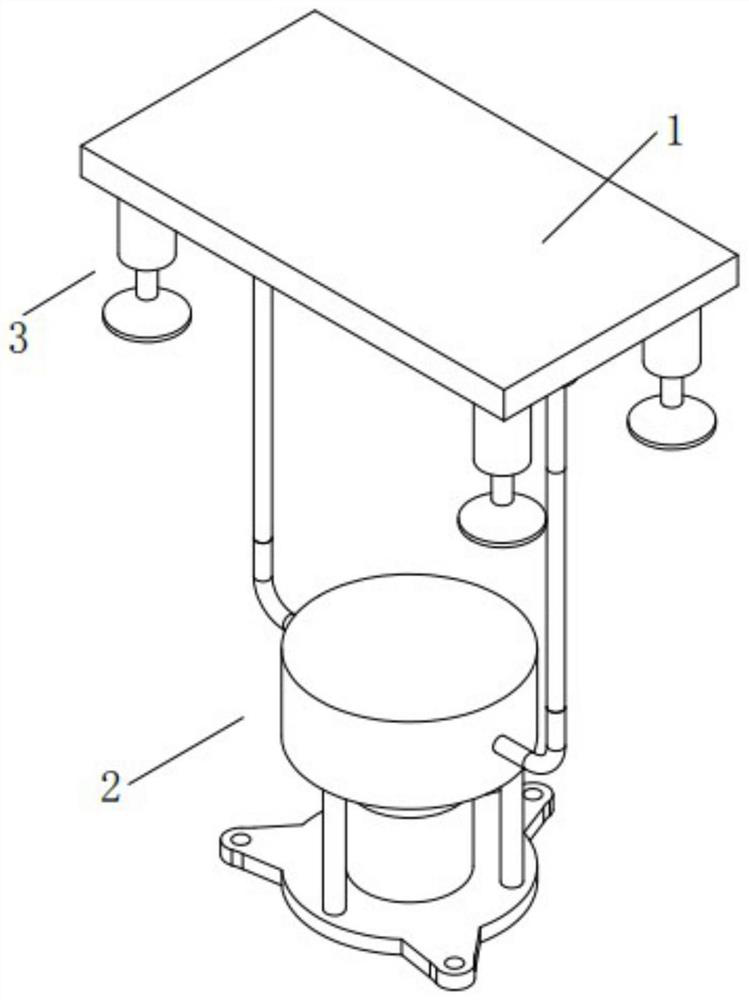
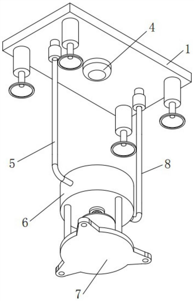
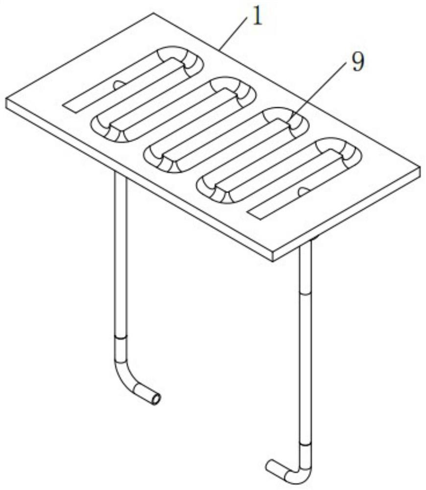
[0031] A heat sink, such as Figure 1-4 As shown, it includes an alloy substrate 1 and a cooling liquid circulation mechanism 2, the cooling liquid circulation mechanism 2 is arranged in cooperation with the alloy substrate 1, an S-shaped channel 9 is reserved inside the alloy substrate 1, and the alloy A first connection nozzle 10 and a second connection nozzle 16 are symmetrically and fixedly installed on one side of the substrate 1, the first connection nozzle 10 communicates with one end of the S-shaped passage 9, and the second connection nozzle 16 communicate with the other end of the S-shaped channel 9;

[0032] Such as Figure 2-7As shown, the cooling liquid circulation mechanism 2 includes a base 7, a cylindrical sealed casing 6 filled with cooling liquid, a first connecting pipe 5, a first locking cap 11, a second connecting pipe 8, a second lock Tight cap 15, connecting seat 23, connecting shaft 18, cylindrical mounting seat 19, blade 17 and motor 20, the base 7 i...


PUM


Abstract

The present invention relates to the technical field of heat dissipation, in particular to a heat sink, which includes an alloy substrate and a cooling liquid circulation mechanism. A first connection nozzle and a second connection nozzle are symmetrically and fixedly installed on one side of the alloy substrate. One end of the S-shaped passage is connected, and the second connecting nozzle is connected with the other end of the S-shaped passage. The cooling liquid circulation mechanism includes a base, a cylindrical sealing shell, a first connecting pipe, a first locking cap, and a second connecting pipe. , a second locking cap, a connecting seat, a connecting shaft, a cylindrical mounting seat, blades and a motor. The present invention is relatively convenient to install and has excellent heat conduction and heat dissipation performance. It can use the cooling liquid to cooperate with the alloy substrate to dissipate heat for the part with serious heat inside the communication equipment, which can not only ensure the heat dissipation effect, but also prevent dust from entering the interior of the communication equipment. It can better meet the heat dissipation requirements of the communication equipment, and can effectively ensure the normal operation of the communication equipment.

Description

technical field [0001] The invention relates to the technical field of heat dissipation, and more specifically, it relates to a heat sink. Background technique [0002] Electronic communication equipment includes some equipment including integrated circuits, transistors and electronic tubes, such as routers and some computer-related equipment. These electronic communication equipment will generate a lot of heat during operation. If the heat is not discharged in time, it will affect electronic communication. For the normal operation of the equipment, it is necessary to carry out timely heat dissipation treatment on the electronic communication equipment. The conventional heat dissipation treatment usually uses a cooling fan. The function of the cooling fan is to speed up the air exchange. However, when the electronic equipment generates a lot of heat, The heat dissipation effect of the heat dissipation fan is just difficult to meet the needs, and the heat dissipation effect i...

Claims


Application Information

Patent Timeline
Patent Type & Authority Patents(China)
IPC IPC(8): H05K7/20
CPCH05K7/20254H05K7/20272
Inventor 王学隆
Owner SUZHOU TONGZHUN PRECISION PLASTIC HARDWARE CO LTD
Why Eureka
Try Eureka