
Novel miniature waste processor

A technology for garbage disposal and garbage disposal, which is applied in grain processing, indoor sanitary pipe installations, water supply installations, etc., and can solve the problems of inability to achieve pulverization, high noise and vibration, and easy entanglement of flexible garbage.

Pending Publication Date: 2020-08-21
佛山市顺德区雅仕特厨卫制品有限公司
View PDF0 Cites 0 Cited by
  • Summary
  • Abstract
  • Description
  • Claims
  • Application Information

AI Technical Summary

Problems solved by technology

[0002] The garbage disposers on the market, conventional garbage disposers are driven by high-power motors, and are equipped with a knife head with an impact effect. The knife head relies on high-speed rotation to impact or grind kitchen waste. Although it can crush hard Waste with high noise and vibration and high energy consumption
[0003] After a long-term investigation, it was found that most of the kitchen waste processed by users using garbage processors is flexible kitchen waste (such as skin) or soft food waste (such as fine bones, vegetable and fruit stems, seafood shells, etc.), and hard food waste Kitchen waste (such as large bones) is also relatively large in size, so it may not be able to directly fall into the garbage processor for disposal. Users usually dispose of it by discarding it. For thin and flexible waste (such as skin, etc. ) is easy to wrap around the cutter head and often does not achieve a good crushing effect
[0004] In addition, the interior of conventional garbage disposers is difficult to clean

Method used


Image

  • Novel miniature waste processor
  • Novel miniature waste processor
  • Novel miniature waste processor

Examples


no. 2 example

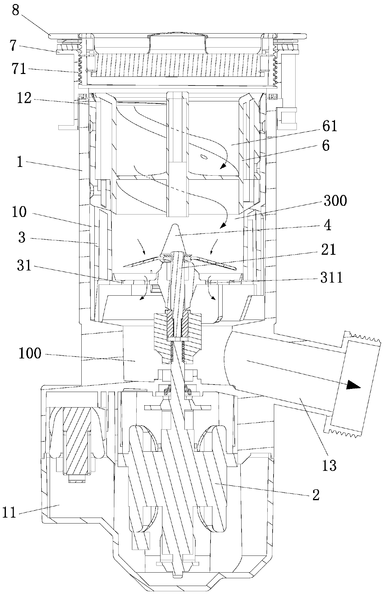
[0031] see Figure 4-Figure 5 The main difference between the new type of micro-garbage disposer and the first embodiment is that the blocking mechanism includes a straight-through ring 51 and a diversion cone 52, and the middle part of the straight-through ring 51 is provided with a straight-through hole (for kitchen waste and kitchen waste). The entry of remaining garbage), which is installed on the upper part of the knife cage 3 and is close to the feed port 12. The guide cone 52 is an inverted cone, which is installed in the middle or lower part of the knife cage 3 and is located at the center of the mixing tool 4. above. The straight-through hole is located on the upper part of the knife cage, and the guide cone 52 is located on the middle and lower parts of the knife cage. The objects entering from the through-hole will be scattered around through the guide cone 52, which can effectively avoid the insertion of human hands, and can also realize The transportation of kitc...


PUM


Abstract

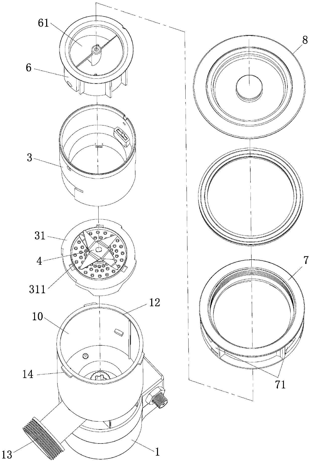
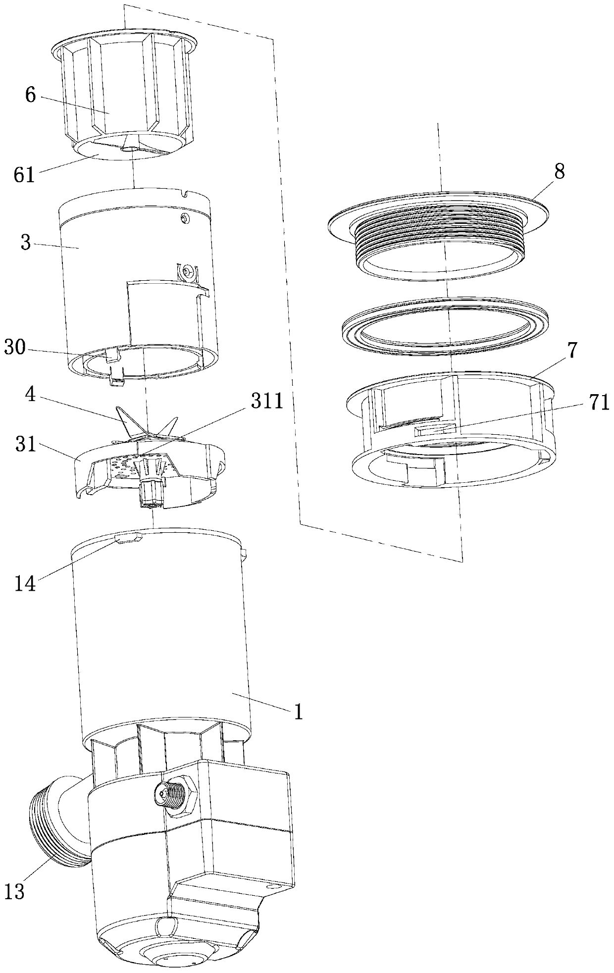
The invention relates to a novel miniature waste processor. The novel miniature waste processor comprises a main machine and a cutter cage. A processing chamber and an electrical chamber are arrangedin the main machine in a separated manner. A feeding inlet is arranged on the top of the processing chamber. A discharging outlet is arranged on the lower part of the processing chamber. A motor is arranged in the electrical chamber. A motor shaft of the motor extends into the processing chamber. The cutter cage is installed in the processing chamber. A cutter holder is arranged at the bottom of the cutter cage. Small material falling holes are distributed in the cutter holder. The motor shaft penetrates into the cutter cage through the cutter holder and is connected with a stirring cutter. The feeding inlet, the cutter cage, the small material falling holes and the discharging outlet are arranged in a sequential communication manner to form a miniature waste processing channel. Accordingto the novel miniature waste processor, the processing chamber or the cutter cage arranged on the main machine can be used to contain food waste liquid and kitchen waste, the stirring cutter can be used to carry out continuous stirring and cutting, and soft kitchen waste can be quickly cut into pieces.

Description

technical field [0001] The invention relates to a novel micro-garbage disposer. Background technique [0002] The garbage disposers on the market, conventional garbage disposers are driven by high-power motors, and are equipped with a knife head with an impact effect. The knife head relies on high-speed rotation to impact or grind kitchen waste. Although it can crush hard Waste, which has a lot of noise and vibration and high energy consumption. [0003] After a long-term investigation, it was found that most of the kitchen waste processed by users using garbage processors is flexible kitchen waste (such as skin) or soft food waste (such as fine bones, vegetable and fruit stems, seafood shells, etc.), and hard food waste Kitchen waste (such as large bones) is also relatively large in size, so it may not be able to directly fall into the garbage processor for disposal. Users usually dispose of it by discarding it. For thin and flexible waste (such as skin, etc. ) is easy to...

Claims


Application Information

Patent Timeline
Patent Type & Authority Applications(China)
IPC IPC(8): B02C18/12B02C18/18E03C1/266
CPCB02C18/0092B02C18/12B02C18/18E03C1/2665B02C2201/06
Inventor 梁升和张洪刚华志文
Owner 佛山市顺德区雅仕特厨卫制品有限公司
Learn More