Circulating cleaning machine for electromechanical equipment parts

A technology for electromechanical equipment and parts, which is applied in the field of circular cleaning machines for electromechanical equipment parts, can solve the problems of reducing the clearance of helical gears and the cleaning effect of the upper surface, and achieve the effect of improving the cleaning effect and preventing reoccurrence of contact

Inactive Publication Date: 2020-08-21
陈新姐
View PDF0 Cites 1 Cited by
  • Summary
  • Abstract
  • Description
  • Claims
  • Application Information

AI Technical Summary

Problems solved by technology

[0002] Helical gears are one of the frequently used parts in electromechanical equipment. During the rotation of helical gears, lubricating oil is often added to reduce the vibration generated during the rotation of helical gears. At the same time, the lubricant will also bring Dirt, you need to use a high-pressure cleaner to clean the surface of the helical gear, but because the helical gear is distributed with inclined serrations, the gap between the serrations is small and the gap is inclined. In the process of high-pressure jet cleaning of the narrow gap It is easy to be blocked by the saw teeth, and the helical gear adheres to a lot of lubricating oil, leaving a layer of oil stains on the water surface after cleaning. When the helical gear is taken out, the upper layer of the helical gear comes into contact with the oil stains, and the oil stains cover the helical gears again. The surface of the helical gear can be reduced and the cleaning effect of the upper surface can be reduced

Method used


Image

  • Circulating cleaning machine for electromechanical equipment parts
  • Circulating cleaning machine for electromechanical equipment parts
  • Circulating cleaning machine for electromechanical equipment parts

Examples


Embodiment 1

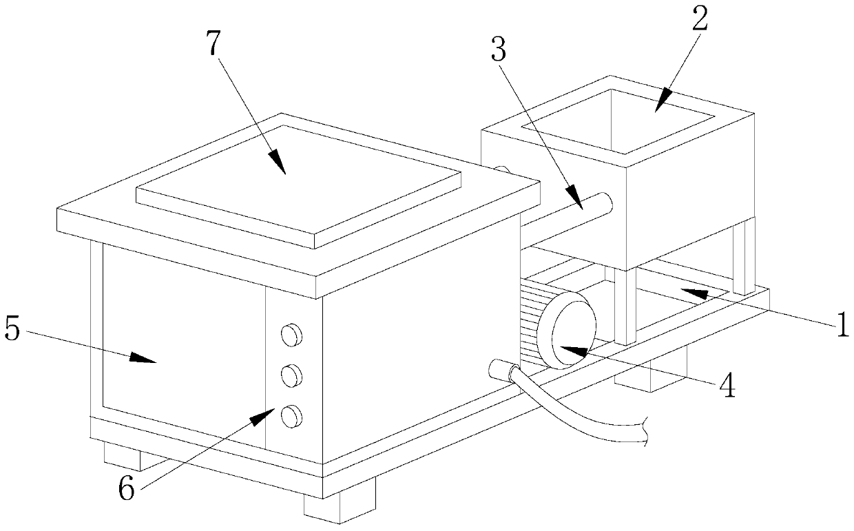
[0022] as attached figure 1 to attach Figure 5 Shown:

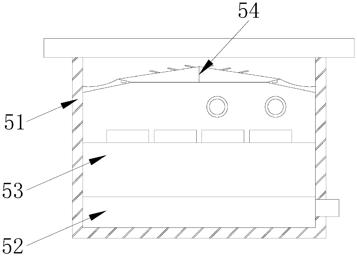
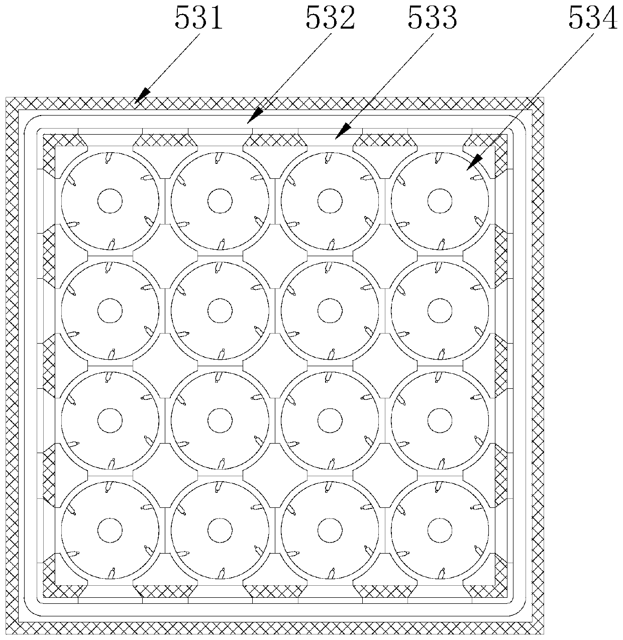
[0023] The present invention is a cycle cleaning machine for mechanical and electrical equipment parts, its structure includes a support frame 1, a water tank 2, a water inlet pipe 3, a water pump 4, a cleaning tank 5, a control panel 6, a top cover 7, the rear end of the support frame 1 and the water tank 2. The lower ends are welded together. The water tank 2 is connected to the cleaning tank 5 through the water inlet pipe 3. The water inlet pipe 3 is connected to the water pump 4. The front surface of the cleaning tank 5 is embedded with a control panel 6, and the top of the cleaning tank 5 is provided with a There is a top cover 7, and the cleaning box 5 includes a box body 51, a high-pressure injection box 52, a placement groove 53, and a top layer separation mechanism 54. A high-pressure injection box 52 is fixedly installed at the bottom of the inner side of the box body 51. The upper end is provided with a plac...

Embodiment 2

[0030] as attached Figure 6 to attach Figure 7 Shown:

[0031] Wherein, the top separation mechanism 54 includes an adhesive plate 541, a card slot 542, a locking rod 543, and a separation diffusion plate 544. There is a slot 542, and the locking rod 543 is installed inside the slot 542 by clearance fit. The locking rod 543 is fixedly installed on the lower left side of the separation diffusion plate 544. There are two adhesive plates 541, and The upper end is provided with a concave curved surface, which is respectively arranged inside the left and right sides of the box body 51, which is beneficial for adhering and placing the oil stains flowing on both sides of the upper layer.

[0032] Wherein, the separation and diffusion plate 544 includes a plate body 44a, a contact frame 44b, a flow port 44c, and a shielding plate 44d. The bottom of the body 44a, the flow port 44c runs through the inside of the plate body 44a, the baffle plate 44d is fixedly installed on the upper...


PUM


Abstract

The invention discloses a circulating cleaning machine for electromechanical equipment parts. The circulating cleaning machine structurally comprises a supporting frame, a water tank, a water inlet pipe, a water pump, a cleaning box, a control panel and a top cover, wherein the rear end of the supporting frame is welded to the lower end of the water tank, water pressure conduction is conducted through a conduction pipe, then pressure division is conducted through a pressure division pipe, water is sprayed into a connecting pipe, the inclined gaps of a bevel wheel sawteeth are sprayed, a bevelgear rotates stably and horizontally through rotation of a rotating plate, so that the bevel gear is prevented from being blocked by the saw teeth easily in the process of high-pressure jet cleaning of the narrow gap, the cleaning effect of dirt in the gaps of the bevel gear is improved, oil stains adhered to the surface of the bevel gear float upwards, oil stains flow to the upper surface of theplate body from flowing openings, flow towards the two sides and then flow to the upper surface of an adhesion plate to be placed in an adhesion mode, the upper layer of the bevel gear is prevented from making contact with the oil stains again, and the cleaning effect of the upper surface layer of the bevel gear is improved.

Description

technical field [0001] The present invention relates to the electromechanical field, and more specifically, relates to a circular cleaning machine for parts of electromechanical equipment. Background technique [0002] Helical gears are one of the frequently used parts in electromechanical equipment. Lubricating oil is often added during the rotation of helical gears to reduce the vibration generated during the rotation of helical gears. At the same time, the lubricant will also bring Dirt, you need to use a high-pressure cleaner to clean the surface of the helical gear, but because the helical gear is distributed with inclined serrations, the gap between the serrations is small and the gap is inclined. In the process of high-pressure jet cleaning of the narrow gap It is easy to be blocked by the saw teeth. At the same time, the helical gear adheres to a lot of lubricating oil, leaving a layer of oil stains on the water surface after cleaning. When the helical gear is taken ...

Claims


Application Information

Patent Timeline
IPC IPC(8): B08B3/02B08B3/14B08B13/00B01D17/025
CPCB01D17/0211B08B3/022B08B3/14B08B13/00
Inventor 陈新姐
Owner 陈新姐
Why Eureka
Try Eureka