
Magnetofluid-driven inchworm-like soft robot

A magnetic fluid and robot technology, applied in manipulators, program-controlled manipulators, additive manufacturing, etc., can solve problems such as changing its own shape and size

Inactive Publication Date: 2020-08-21
JIANGSU UNIV
View PDF6 Cites 5 Cited by
  • Summary
  • Abstract
  • Description
  • Claims
  • Application Information

AI Technical Summary

Problems solved by technology

The environmental adaptability of ultra-redundant robots has been greatly improved, but its parts are still rigid bodies, and it is impossible to change its own shape and size

Method used


Image

  • Magnetofluid-driven inchworm-like soft robot
  • Magnetofluid-driven inchworm-like soft robot
  • Magnetofluid-driven inchworm-like soft robot

Examples


Embodiment 1

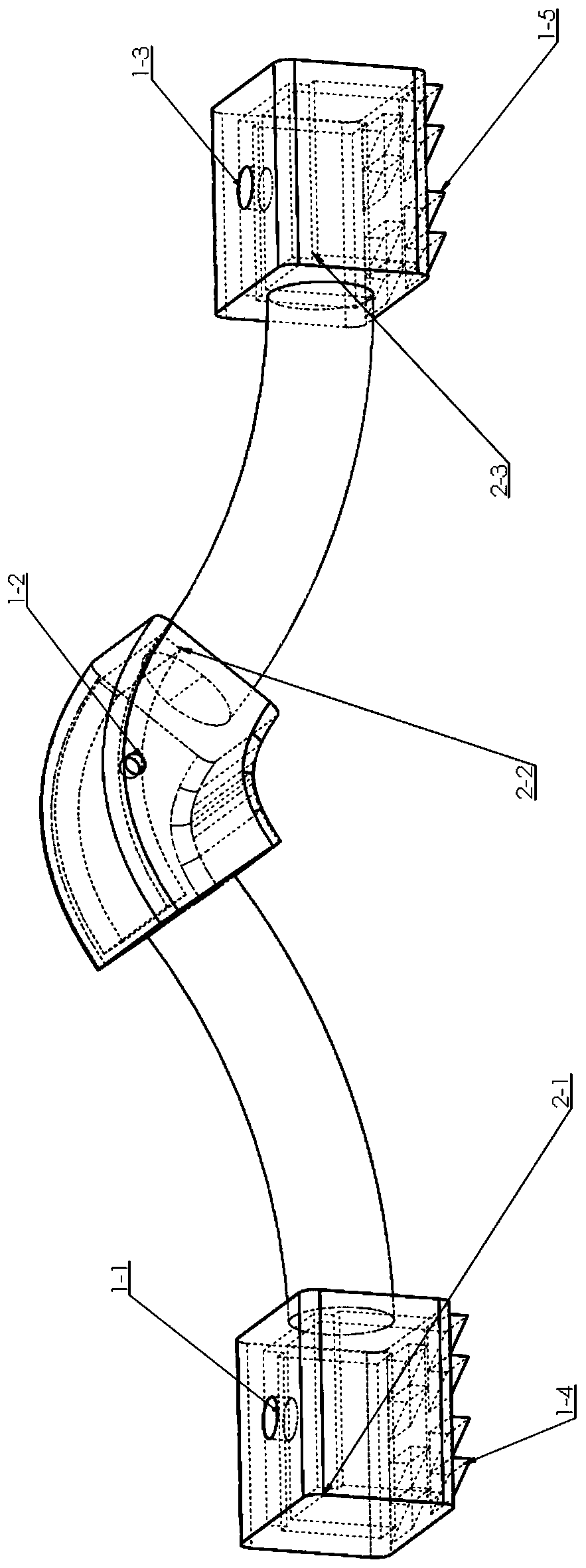
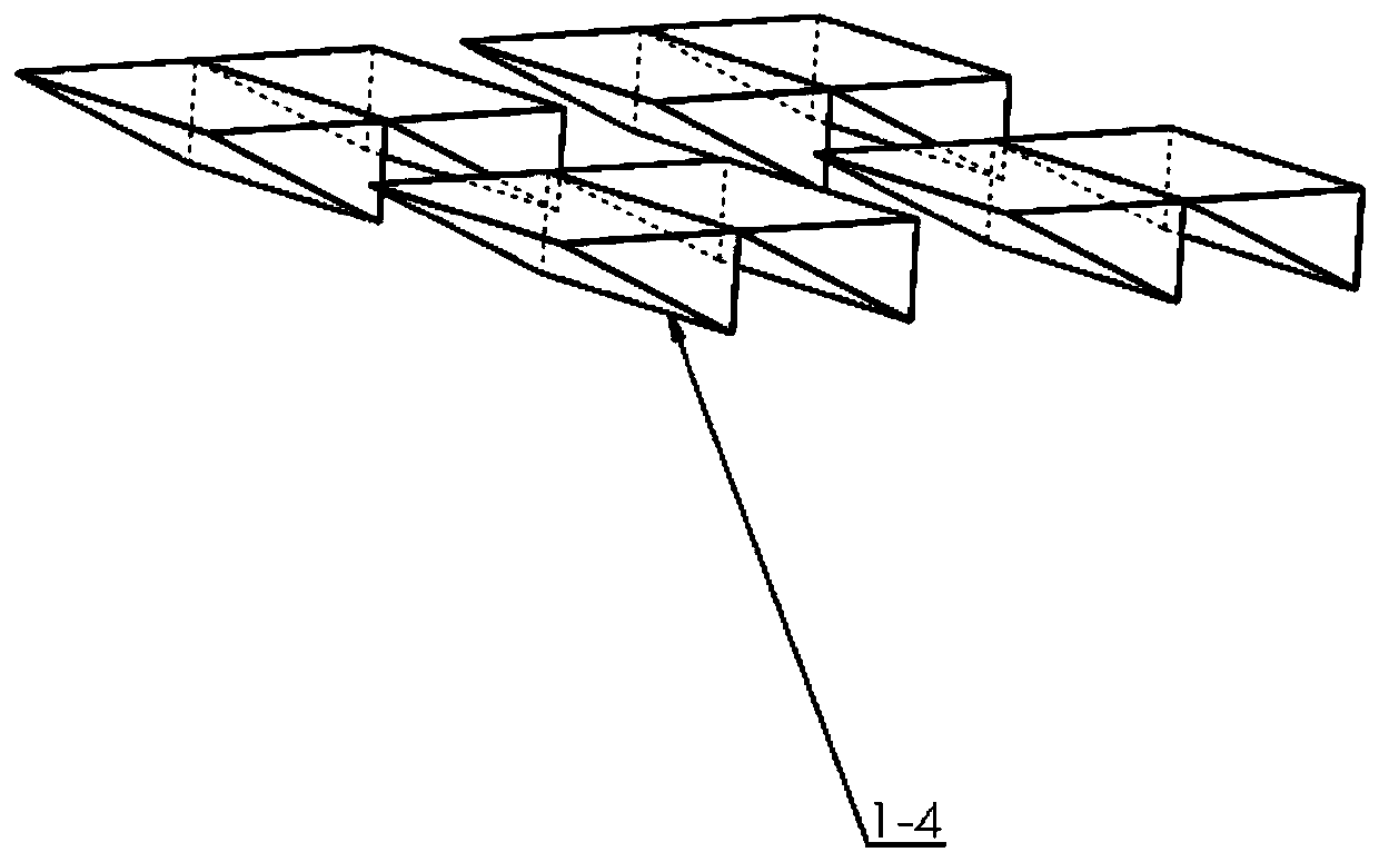
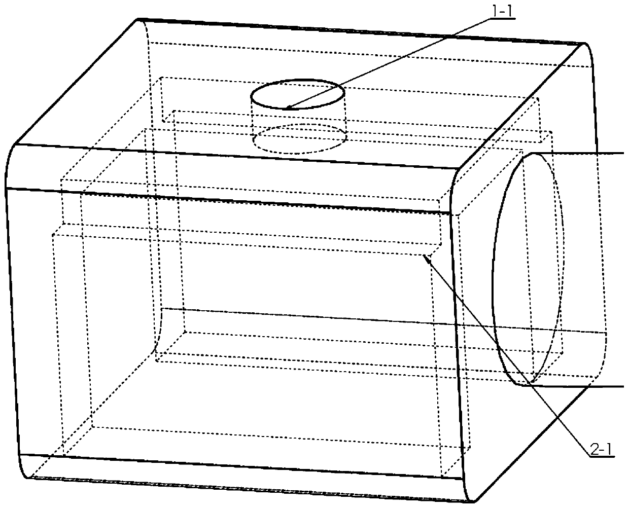
[0027] The design process of the three-dimensional model of the soft robot is: using Solidworks software to design the three-dimensional model of the robot imitating the inchworm robot driven by magnetic fluid, the model includes a head part, a torso part and a tail part, such as figure 1 shown. The size of the head part and the tail part is 20mmX20mmX30mm, the cross-sectional diameter of the two solid tubular torsos is 10mm, and the arc length is 40mm. . Such as figure 1 , figure 2 , image 3 , Figure 4 As shown, footing groups 1-4 and 1-5 with triangular cross-sections are respectively arranged on the bottom surface of the head part and the tail part, wherein 2 triangular prisms (4mmX2mmX4mm) form a group, and the bottom surfaces of the head part and the tail part are respectively arranged 4 groups, all the triangles have the same orientation, and are used for crawling on the ground. The head part and the tail part are respectively provided with a head cavity 2-1 and...

Embodiment 2

[0029] The 3D printing manufacturing process of the inchworm-like soft robot is: using polyurethane acrylate (PUA) and 2,4,6 (trimethylbenzoyl) diphenylphosphine oxide (TOP) as prepolymers of photosensitive resins respectively and photoinitiator, the two are deployed into photosensitive resin with a mass fraction of 95% and 5%; the slice thickness of the 3D printer printing model is set to be 0.1mm, and the designed three-dimensional model is imported into the 3D printing device (preheated to 30 ° C to start Printing, automatic heating to 35°C to maintain a constant temperature, laser characteristics: EN 60825-1:2007 certified Class 1 laser product 405nm violet laser, 250mW laser; laser spot size: 140μm; peeling mechanism: wiper sliding peeling process), completed Forming of the overall structure of the soft robot (printing time depends on the size of the model and its structural complexity). After the printing is completed, take out the elastic body and go through cleaning, w...


PUM


Abstract

The invention provides a magnetofluid-driven inchworm-like soft robot. The robot comprises a head component, a trunk component and a tail component. The head component and the tail component are located at the two ends of the trunk component correspondingly and are centrosymmetric with respect to the truck component. Triangular standing feet in the same direction are arranged on the bottom surfaces of the head component and the tail component correspondingly, and meanwhile, cavities are formed in the head component and the tail component correspondingly so that magnetofluid can be stored. Thetrunk component is divided into two categories which are the solid tubular trunks and the arc-shaped trunk located in the center. One ends of the two solid tubular trunks with circular cross sectionsare in sealed connection with the two ends of the arc-shaped trunk correspondingly, and the trunk component is in an arc shape as a whole. The other ends of the two solid tubular trunks with the circular cross sections are connected and sealed to the head component and the tail component correspondingly. A cavity is formed in the arc-shaped trunk and used for storing magnetofluid. Twisting steering is achieved by applying a transverse electric field to the head or the tail by the outside, and the robot can imitate an inchworm and advances in a stretching-out and drawing-back mode by applying alongitudinal electric field to the trunks by the outside.

Description

technical field [0001] The invention relates to the fields of unfettered driving and soft robots, in particular to a magnetic fluid-driven soft robot imitating an inchworm. Background technique [0002] Robotics (Robotics) is the science of building machines with the required motor, perception, and cognitive abilities. Robots are machines designed to serve humans. With the continuous development of the times, people's demand for robots is increasing day by day, and the requirements are also increasing. Now robots have been widely used in military, industrial, aviation and many other fields. Traditional robots are generally composed of rigid modules connected by kinematic pairs, and each degree of freedom provides one (or more) translational or rotational degrees of freedom. The movement combination of all kinematic pairs forms the working space of the robot end effector, so this type of robot has the advantage of precise movement, but its shortcomings are also exposed. The...

Claims


Application Information

Patent Timeline
Patent Type & Authority Applications(China)
IPC IPC(8): B25J9/06B25J9/14B29C64/124B29C64/268B29C64/379B33Y80/00B33Y10/00B33Y70/00B33Y40/20B33Y30/00B29K75/00B29K105/00
CPCB25J9/065B25J9/14B29C64/124B29C64/268B29C64/379B33Y80/00B33Y10/00B33Y70/00B33Y40/20B33Y30/00B29K2075/00B29K2105/0005
Inventor 杨凯王晓东薄智辉程广贵徐琳张忠强
Owner JIANGSU UNIV
Learn More