Electric cutting tool

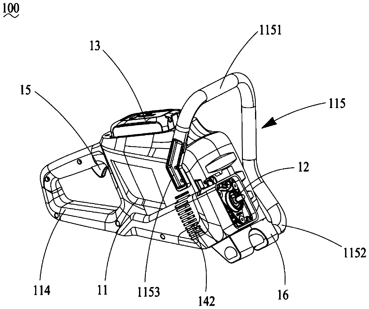
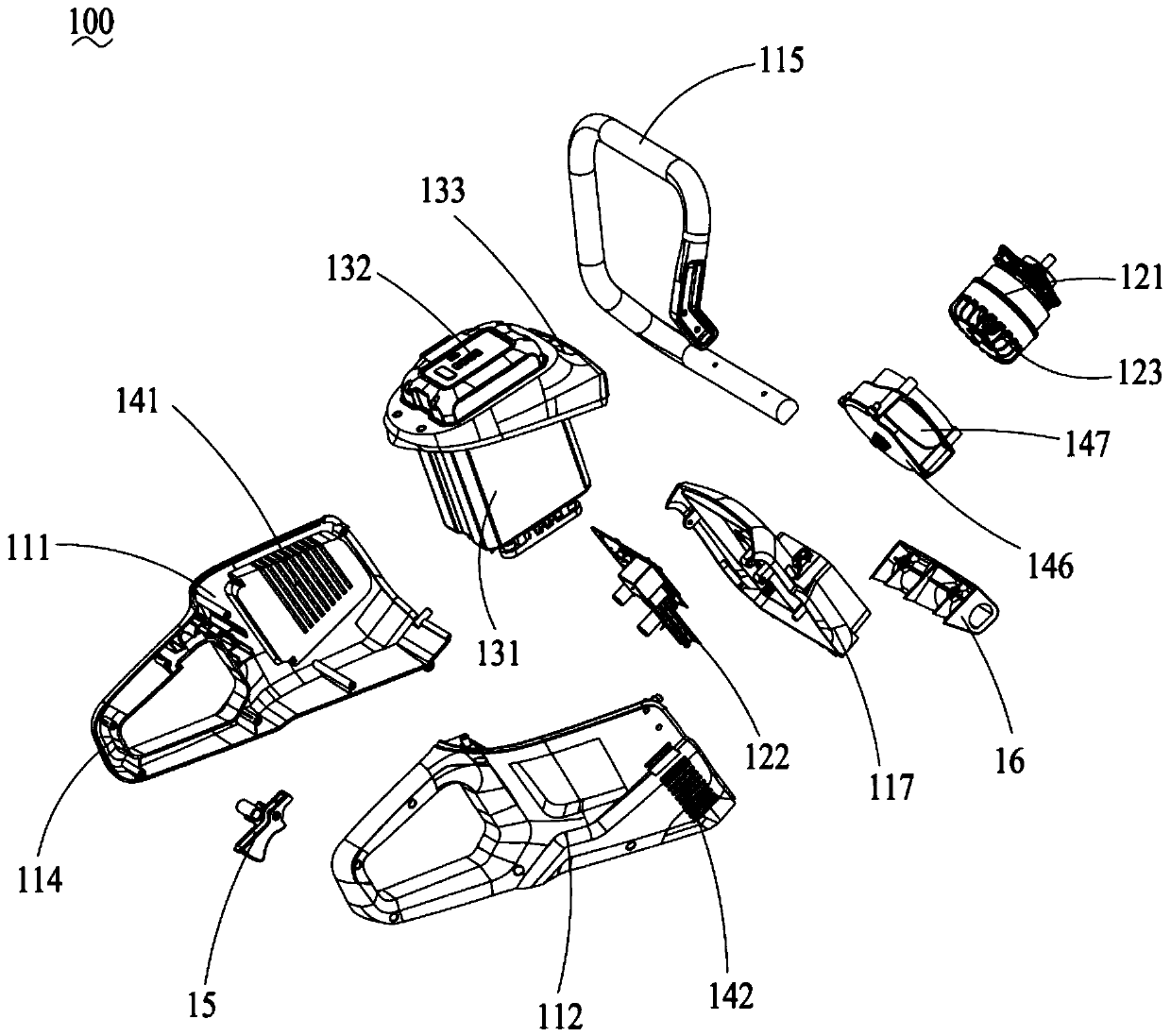
A cutting tool and electric technology, which is applied in the direction of manufacturing tools, stone processing tools, wood processing appliances, etc., can solve the unfavorable problems such as the miniaturization of electric cutting tools, the inaccurate laying of cooling pipelines, and the limited promotion of electric cutting tools. To achieve the effect of compact structure, small space occupation and extended service life

Pending Publication Date: 2020-08-21
CHANGZHOU GLOBE CO LTD
View PDF0 Cites 2 Cited by
  • Summary
  • Abstract
  • Description
  • Claims
  • Application Information

AI Technical Summary

Problems solved by technology

[0004] Although the existing high-power hand-held electric cutting tools have a corresponding cooling structure, the conventional cooling structure usually only cools the drive motor. In the prior art, water cooling is used to spray the cutter blade while cooling the The internal motor is cooled, but because the water-cooling structure needs to provide complex water-cooling pipelines, on the one hand, the cooling pipeline cannot be accurately laid to various positions of the electric cutting tool, resulting in limited cooling effect; on the other hand, the laying of the cooling pipeline will lead to The increase in volume of electric cutting tools is not conducive to the miniaturization of electric cutting tools, resulting in limited popularization of electric cutting tools in the prior art

Method used


Image

  • Electric cutting tool
  • Electric cutting tool
  • Electric cutting tool

Examples


Embodiment Construction

[0028] In order to make the object, technical solution and advantages of the present invention clearer, the present invention will be described in detail below in conjunction with the accompanying drawings and specific embodiments.

[0029] Examples of these preferred embodiments are illustrated in the accompanying drawings. The embodiments of the invention shown in and described with reference to the drawings are merely exemplary, and the invention is not limited to these embodiments.

[0030] Here, it should also be noted that, in order to avoid obscuring the present invention due to unnecessary details, only the structures and / or processing steps closely related to the solution of the present invention are shown in the drawings, and the steps related to the present invention are omitted. Invent other details that don't really matter.

[0031] Additionally, it should be noted that the term "comprises", "comprises" or any other variation thereof is intended to cover a non-ex...


PUM


Abstract

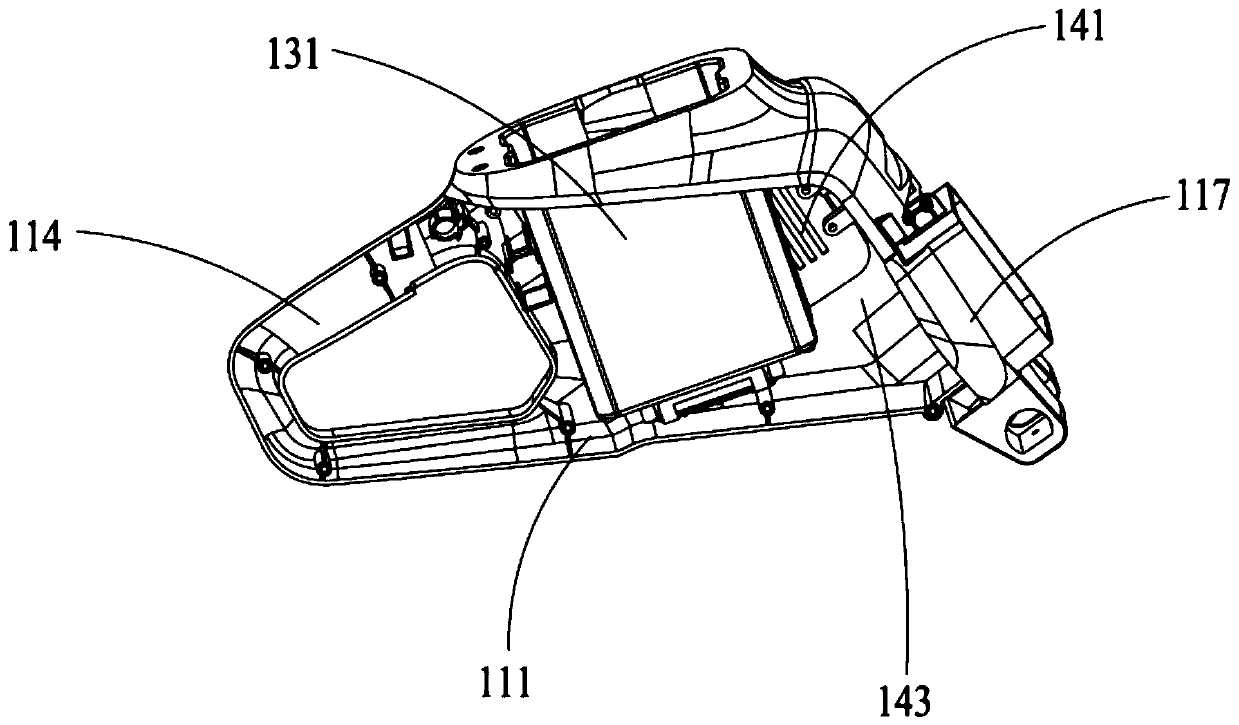
The invention provides an electric cutting tool. The electric cutting tool comprises a working assembly and a controlling assembly used for controlling the working assembly; the working assembly comprises a shell body, a driving unit and a power supply unit; a cooling structure is formed inside the shell body and is used for cooling the driving unit and the power supply unit; the cooling structurecomprises an air inlet, an air outlet, and a cooling air duct, and the air inlet is arranged on a first shell body, the air outlet is arranged on a second shell body, and the cooling air duct connects the air inlet and the air outlet; the driving unit comprises a fan which protrudes into the cooling air duct; and the fan drives cooling air outside the controlling assembly to flow through the airinlet, along the cooling air duct, into the power supply unit and the driving unit and flow out of the air outlet. Through the arrangement of the controlling assembly which is provided with the cooling structure, the provided electric cutting tool realizes effective cooling of the driving unit and the power supply unit which are contained in the shell body; the working efficiency of the electric cutting tool using the controlling assembly is improved; the service life is extended; and at the same time, a tight structure, smaller occupied space and convenient operation are guaranteed.

Description

technical field [0001] The invention relates to an electric cutting tool. Background technique [0002] An electric cutting tool is a portable cutting tool that cuts materials such as stone, concrete or wood using a cutting disc that is rotatably mounted on a stand. [0003] In fact, in order to facilitate the operation and use of high-power hand-held electric cutting tools, it is necessary to achieve small size and have a good cooling effect at the same time, so as to further ensure the use effect of high-power hand-held electric cutting tools. [0004] Although the existing high-power hand-held electric cutting tools have a corresponding cooling structure, the conventional cooling structure usually only cools the drive motor. In the prior art, water cooling is used to spray the cutter blade while cooling the The internal motor is cooled, but because the water-cooling structure needs to provide complex water-cooling pipelines, on the one hand, the cooling pipeline cannot b...

Claims


Application Information

Patent Timeline
Patent Type & Authority Applications(China)
IPC IPC(8): B28D1/22B28D7/00B28D7/02B27C5/00
CPCB27C5/00B28D1/228B28D7/00B28D7/02
Inventor 王海滨张林高
Owner CHANGZHOU GLOBE CO LTD
Why Eureka
Try Eureka