An electric pole bracket
A technology for utility poles and electric push rods, applied in the field of utility pole brackets, can solve the problems of small static friction at the contact between the support device and the ground, inability to adjust the recess, unstable support, etc., to achieve convenient daily maintenance, simple structure, and support Strong support
- Summary
- Abstract
- Description
- Claims
- Application Information
AI Technical Summary
Problems solved by technology
Method used
Image
Examples
Embodiment 1
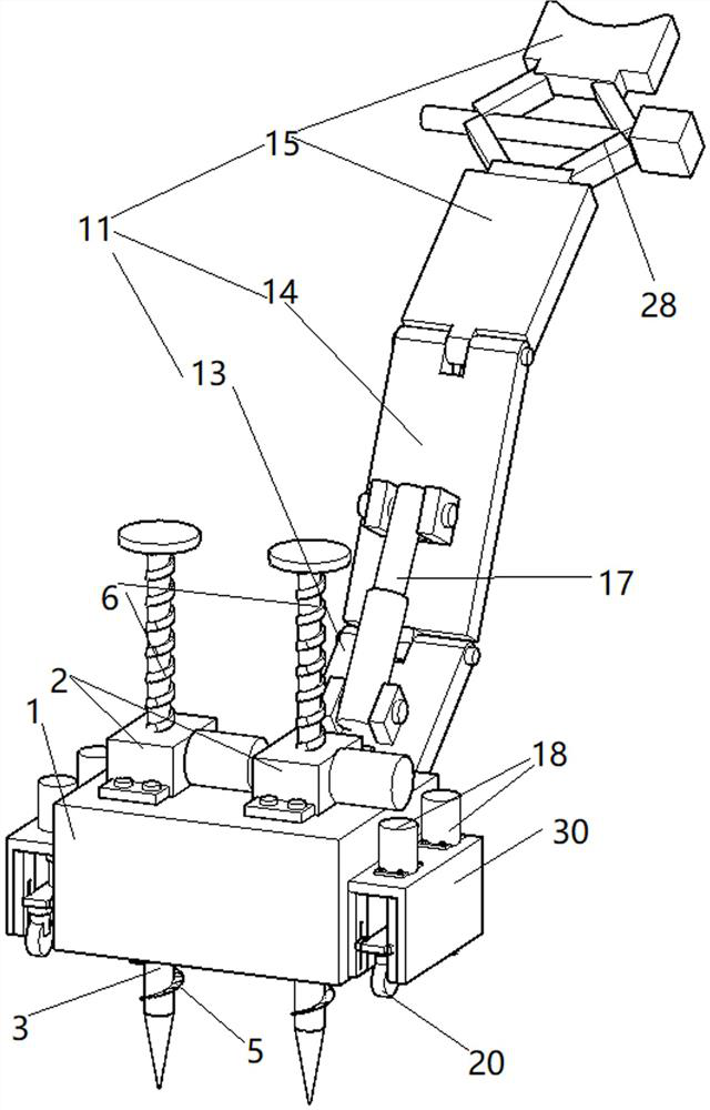
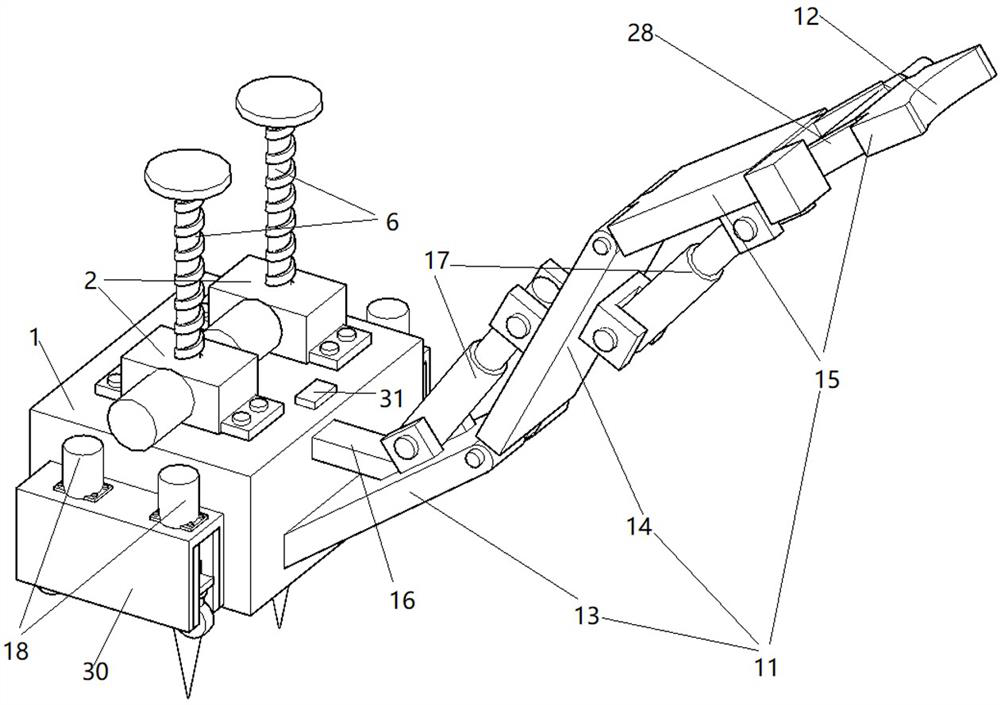
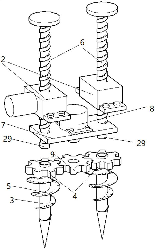
[0031] Such as Figure 1-4 Shown is the first embodiment of the present invention, a utility pole bracket, including a fixed box 1, the fixed box 1 is a cuboid shell-shaped structure welded by eight steel plates, and two spirals are fixed on the top plate of the fixed box 1 The motor of lift 2, such as image 3 As shown, the lower end of the screw rod 6 of the screw jack 2 is located in the fixed box, the screw rod 6 is perpendicular to the ground, and the screw rod 6 is provided with an anti-rotation groove. The bottom end of the screw rod 6 is rotated to connect the connecting rod 3, and the connection method is as follows: a bearing 29 is welded on the bottom end of the screw rod 6, and the bearing 29 is a deep groove ball bearing. The upper part of the connecting rod 3 is welded to the gear one 4, and the middle part of the connecting rod 3 is welded to the spiral blade 5. The radius of the spiral blade 5 gradually decreases from top to bottom. Get two through holes 1 th...
Embodiment 2
[0035] Such as Figure 5 with Image 6 Shown is the second embodiment of the present invention. The difference between this embodiment and Embodiment 1 is that the left side of the fixed box 1 is provided with an accommodation box 22, and the accommodation box 22 is a rectangular parallelepiped shell-like structure with openings at both ends. The accommodation box 22 The right side plate is welded on the fixed box 1 left side wall, and the bottom surface of the accommodation box 22 and the bottom surface of the fixed box 1 are located on the same plane. Moving plate 23 is set in the accommodation box 22, and moving plate 23 is a rectangular plate, and a plurality of ground nails 26 are evenly welded on the bottom surface of the moving plate 23, and the through holes 27 matched with the ground nails are punched out on the bottom surface of the accommodation box 22 by a puncher. The driving device that drives the moving board 23 to move up and down is set on the top surface of ...
Embodiment approach
[0038] Such as Figure 7 Shown is the third embodiment of the present invention. The difference between this embodiment and Embodiment 1 is that the left side of the fixed box 1 has an opening, the opening is hinged to close the door 21, and the other end of the closed door 21 is fixed by a door lock. Box 1 is detachably connected.
PUM
 Abstract
Description
Claims
Application Information
 - R&D
- Intellectual Property
- Life Sciences
- Materials
- Tech Scout
- Unparalleled Data Quality
- Higher Quality Content
- 60% Fewer Hallucinations
Browse by: Latest US Patents, China's latest patents, Technical Efficacy Thesaurus, Application Domain, Technology Topic, Popular Technical Reports.
© 2025 PatSnap. All rights reserved.Legal|Privacy policy|Modern Slavery Act Transparency Statement|Sitemap|About US| Contact US: help@patsnap.com


