Air tightness detection instrument for water-cooled motor

A technology of air tightness detection and water-cooled motors, which is applied in the direction of liquid-tightness measurement using liquid/vacuum degree, and by measuring the increase and deceleration rate of fluid, etc., which can solve the problems of high pressure of water-cooled motor casing, difficult movement of the device, and high cost , to achieve the effects of improving detection stability, improving mobile efficiency, and increasing security

Inactive Publication Date: 2020-08-21
黄茴茴
View PDF0 Cites 2 Cited by
  • Summary
  • Abstract
  • Description
  • Claims
  • Application Information

AI Technical Summary

Problems solved by technology

This kind of water-cooled motor needs to be tested for water leakage in the shell cavity before leaving the factory. In the prior art, a water-cooled motor casing air-tightness tester is used for testing, but the cost of this equipment is relatively high, and only one piece can be tested at a time. very low
[0003] There is a device that can effectively realize automatic transportation of water-cooled motor casings, reliable fixation of water-cooled motor casings, and airtight detection of waterproof motors, and can simultaneously detect multiple water-cooled motor casings, effectively improving The detection efficiency of the water-cooled motor casing; however, after the device is fed with gas, the pressure in the water-cooled motor casing will be too high during the continuous inflation process, which will cause the water-cooled motor casing to detach and affect the detection of the water-cooled motor casing. will cause an explosion
[0004] There is an existing device that can effectively realize the effect of releasing the gas pressure in the water-cooled motor casing, so as to avoid the excessive gas pressure in the water-cooled motor casing and cause the water-cooled motor casing to detach or even explode, increasing the device's Safety, very simple and practical; however, the device is not easy to move, has many limitations, and cannot quickly move to the place where it is needed for work, which is very troublesome

Method used


Image

  • Air tightness detection instrument for water-cooled motor
  • Air tightness detection instrument for water-cooled motor
  • Air tightness detection instrument for water-cooled motor

Examples


Embodiment Construction

[0028] In order to enable those skilled in the art to better understand the solutions of the present invention, the technical solutions in the embodiments of the present invention will be clearly and completely described below in conjunction with the drawings in the embodiments of the present invention. Obviously, the described embodiments are only It is a part of embodiments of the present invention, but not all embodiments. Based on the embodiments of the present invention, all other embodiments obtained by persons of ordinary skill in the art without making creative efforts shall fall within the protection scope of the present invention.

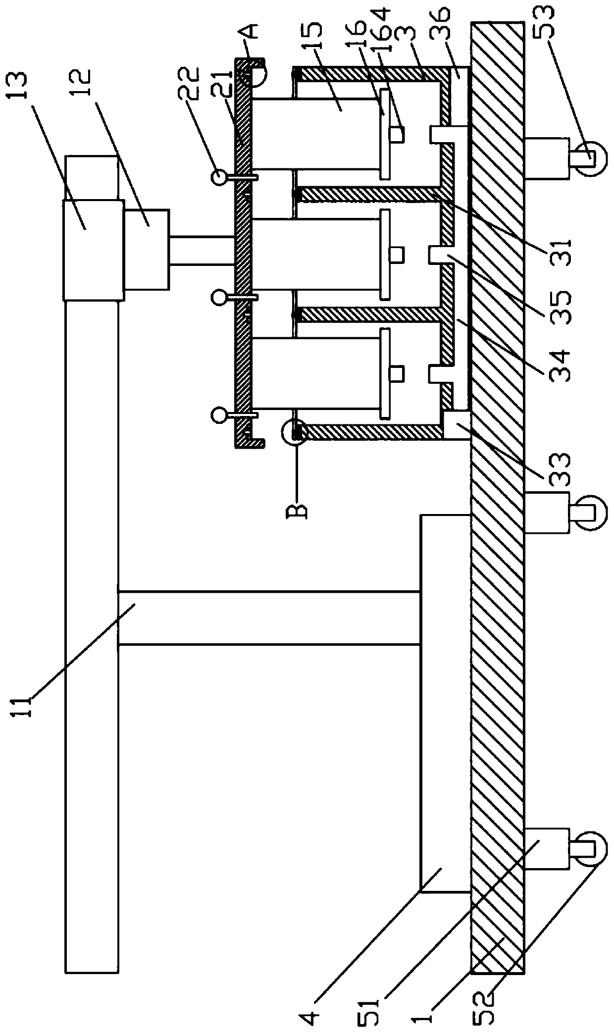
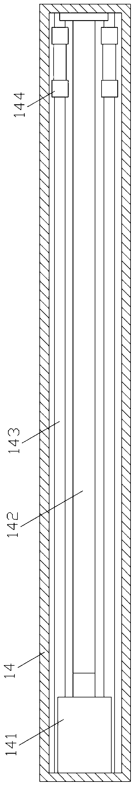
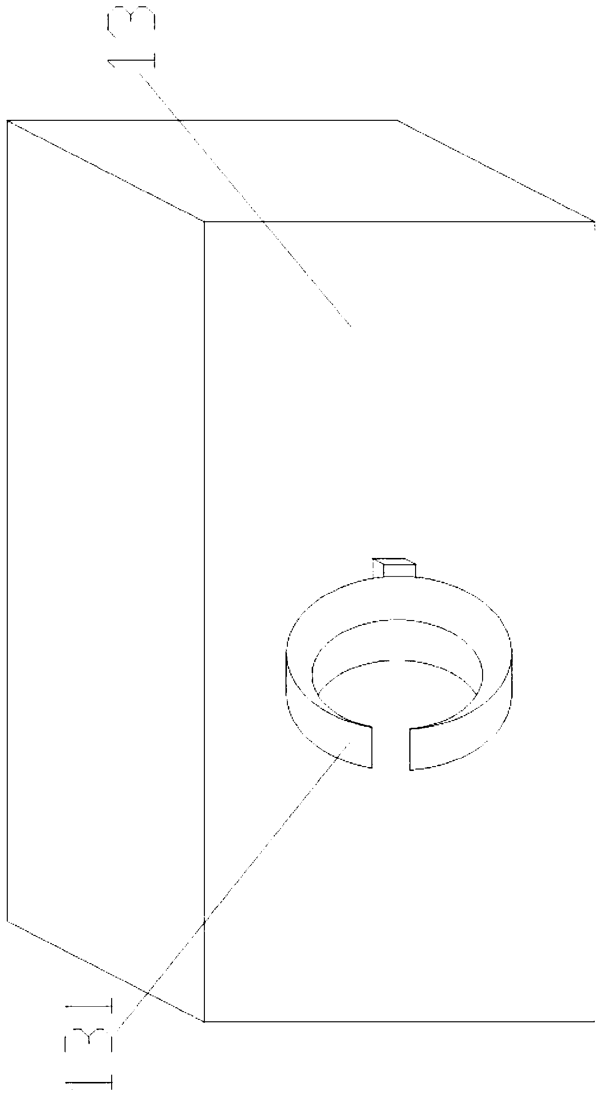
[0029] like Figure 1-14 As shown, a water-cooled motor air tightness testing instrument includes a fixed base 1, a driving mechanism, a fixing mechanism and a detection mechanism are arranged above the fixed base 1, and the fixing mechanism and the detection mechanism are matched, and the above-mentioned driving mechanism is used for Dr...


PUM


Abstract

The invention discloses an air tightness detection instrument for a water-cooled motor. The instrument comprises a fixed base, and a fixing mechanism and a detection mechanism are arranged above the fixed base; the detection mechanism comprises a gas transmission device, a pressure release valve is arranged at the tail end of the gas transmission device, a plurality of moving mechanisms are arranged at the bottom of the fixed base at equal intervals, and each moving mechanism comprises a connecting block fixedly connected with the bottom of the fixed base and a moving device arranged below theconnecting block. Through the arrangement of the moving mechanisms, the instrument can be effectively moved, so that the instrument can be moved to a required place at any time, the application rangeof the device is enlarged, and the practicability of the device is enhanced.

Description

technical field [0001] The invention belongs to the field of leak-proof detection of motor casings, and in particular relates to a water-cooled motor air-tightness detection instrument. Background technique [0002] The casing of the water-cooled motor in the form of casing water cooling has a sealed cavity, and there are water inlet holes and drain holes on the cavity. The water hole flows into the cavity of the casing, and the cooling circulating water exchanges heat with the casing when passing through the casing, thereby achieving the effect of cooling the motor. This kind of water-cooled motor needs to be tested for water leakage in the shell cavity before leaving the factory. In the prior art, a water-cooled motor casing air-tightness tester is used for testing, but the cost of this equipment is relatively high, and only one piece can be tested at a time. very low. [0003] There is a device that can effectively realize automatic transportation of water-cooled motor ...

Claims


Application Information

Patent Timeline
Patent Type & Authority Applications(China)
IPC IPC(8): G01M3/26
CPCG01M3/26
Inventor 黄茴茴
Owner 黄茴茴
Why Eureka
Try Eureka