Whirling tool

A tool and cutting edge technology, applied in the field of rotary cutting tools, which can solve problems such as the limitation of coolant flow direction, and achieve the effect of reducing wear, high surface quality, and improving chip removal.

Active Publication Date: 2020-08-21
HARTMETALL WERKZEUGFAB PAUL HORN
View PDF11 Cites 1 Cited by
  • Summary
  • Abstract
  • Description
  • Claims
  • Application Information

AI Technical Summary

Problems solved by technology

Therefore, reliable cooling of the cutting insert and / or cutting edge cannot always be ensured
Similarly, the direction of coolant flow is often significantly restricted due to external coolant supplies

Method used


Image

  • Whirling tool
  • Whirling tool
  • Whirling tool

Examples


Embodiment Construction

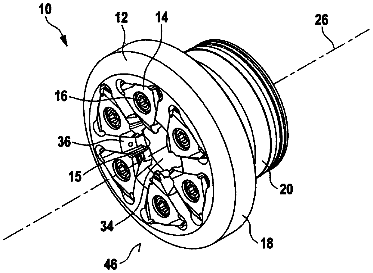
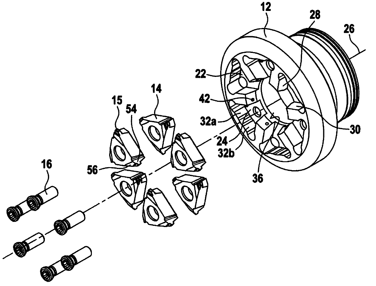
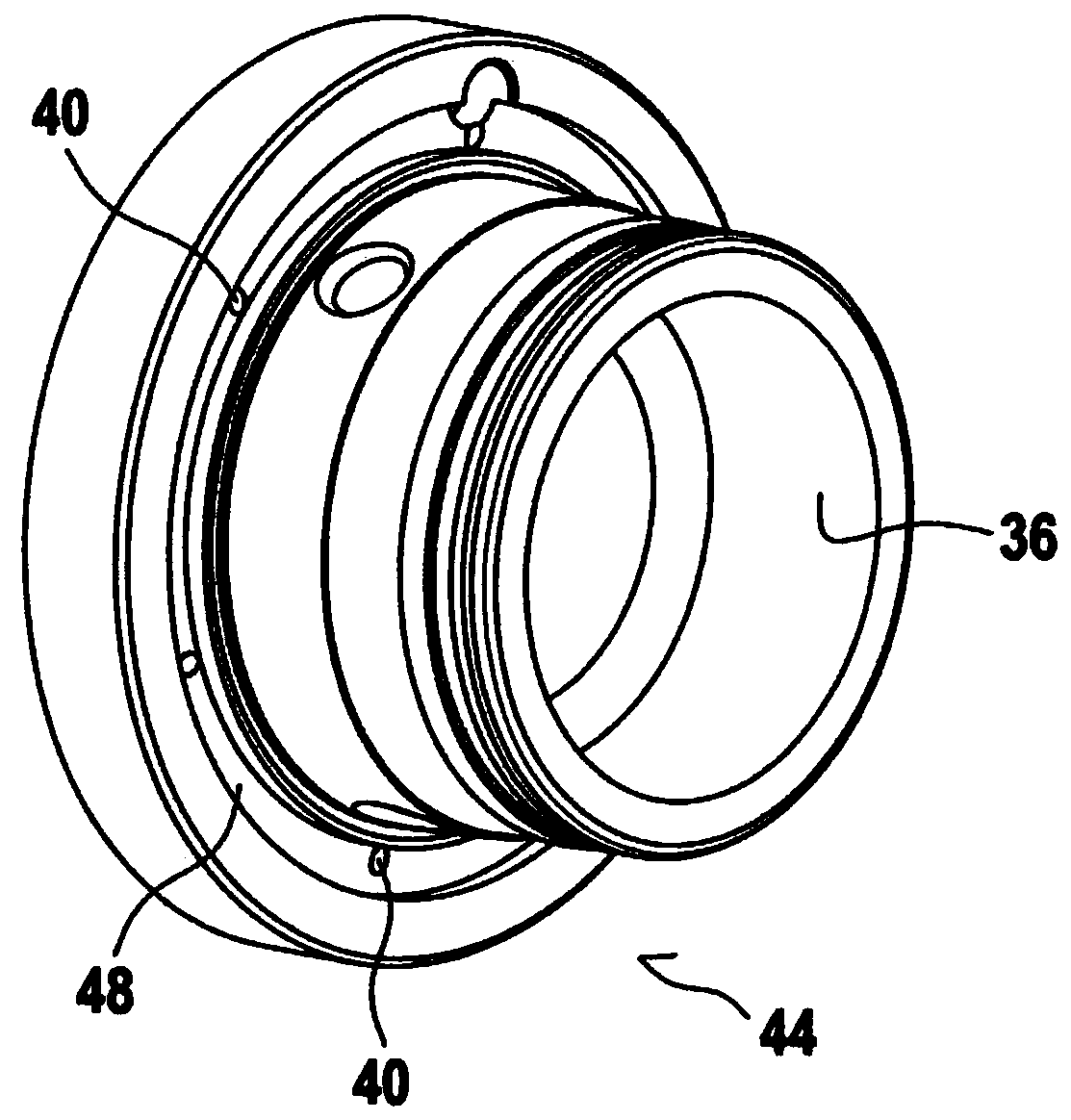
[0058] Figure 1 to Figure 18 Four different exemplary embodiments of rotary cutting tools according to the invention are shown. This exemplary embodiment differs substantially in the design of the internal coolant channels provided in the interior of the rotary cutting tool. Furthermore, there are small structural differences between the exemplary embodiments, especially with respect to the design of the connection flange of the rotary cutting tool, but these differences are not highlighted with respect to the present invention.

[0059] According to the rotary cutting tool of the present invention in Figure 1-18 The whole is indicated by reference numeral 10 .

[0060] The rotary cutting tool 10 includes a cutting blade carrier 12 to which a plurality of cutting blades 14 are releasably secured by fastening elements 16 . The cutting insert 14 is preferably an indexable insert made of hard metal. The fastening screw 16 is preferably configured as a self-tapping screw whi...


PUM


Abstract

The invention relates to a whirling tool (10) for machining a workpiece, comprising: a plurality of cutting plates (14), each of the cutting plates (14) having at least one cutter (15); a cutting plate carrier (12) having a plurality of cutting plate holders (22) for holding and releasable fastening of a respective one of the cutting plates (14), the cutting plate holders (22) being arranged suchthat the cutting plates are distributed in the circumferential direction over the cutting plate carrier(12). The cutting plate carrier (12) has a through opening (34) which extends along a central axis (26) of the cutting plate carrier (12) and through which the workpiece can be passed during the machine, and in the installed state the cutting plates (14) protrude into the through opening (34). The tool also comprises a coolant channel (38) which is arranged in the cutting plate carrier (12) and extends between an inlet opening (40) and an outlet opening (42), the outlet opening (42) leading into the through opening (34) and / or being oriented in the direction of the through opening (34).

Description

technical field [0001] The invention relates to a rotary cutting tool for machining workpieces. The rotary cutting tool according to the invention comprises a plurality of cutting inserts, wherein each of the cutting inserts comprises at least one cutting edge. The rotary cutting tool according to the present invention further comprises a cutting blade holder comprising a plurality of cutting blade housings for receiving and releasably fastening the blades respectively. One of the cutting inserts, wherein the cutting insert receiving portions are arranged to be distributed on the cutting insert holder in the circumferential direction, wherein the cutting insert holder comprises a through-opening along the cutting blade The center axis of the insert carrier extends and the workpiece can pass through the through-opening during machining, and wherein in the mounted state the cutting insert protrudes into the through-opening. Background technique [0002] A universal rotary cu...

Claims


Application Information

Patent Timeline
Patent Type & Authority Applications(China)
IPC IPC(8): B23G1/34B23G5/18B23G5/00B23C5/20B23C5/28
CPCB23G1/34B23G5/005B23G5/18B23C5/205B23C5/28B23C2200/367B23C2210/503B23C2220/68B23G2200/12B23G2240/60B23C5/20B23G5/00B23B27/10B23B27/1611B23C5/08B23Q11/10B23B2220/52
Inventor 马库斯·坎威舍尔
Owner HARTMETALL WERKZEUGFAB PAUL HORN
Why Eureka
Try Eureka