Thrombus thrombolysis and clearing device and use method thereof

A device for removing thrombus and a technology for removing thrombus, applied in the field of medical devices, can solve problems such as difficulty in removing thrombus, incomplete removal of thrombus, etc., and achieve the effect of complete removal

Active Publication Date: 2020-08-25
黑龙江省医院
View PDF7 Cites 9 Cited by
  • Summary
  • Abstract
  • Description
  • Claims
  • Application Information

AI Technical Summary

Problems solved by technology

[0003] The purpose of the present invention is to solve the problem that the existing thrombus removal device is difficult to remove ...

Method used


Image

  • Thrombus thrombolysis and clearing device and use method thereof
  • Thrombus thrombolysis and clearing device and use method thereof
  • Thrombus thrombolysis and clearing device and use method thereof

Examples


Embodiment 1

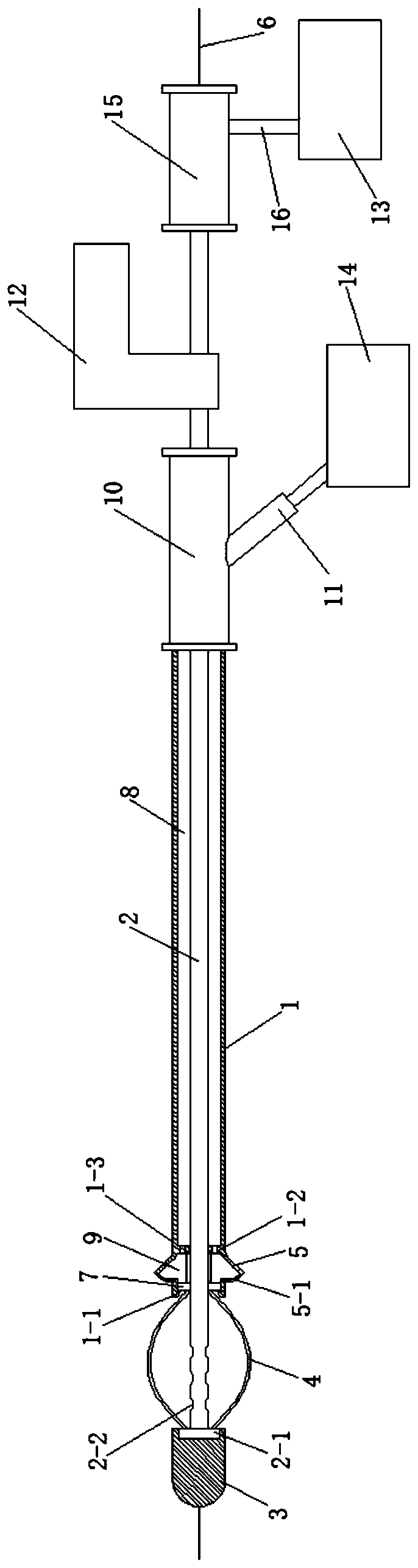
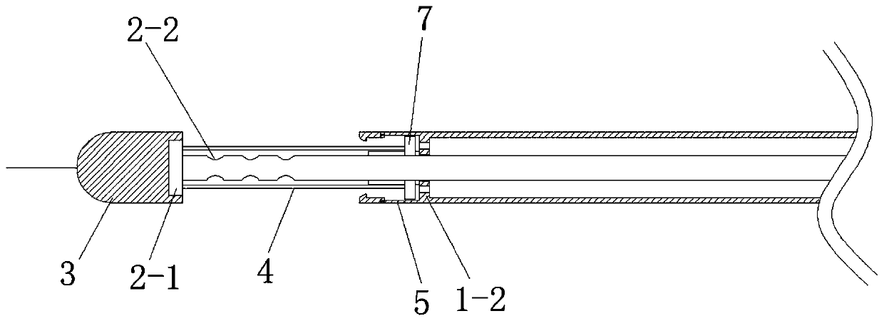
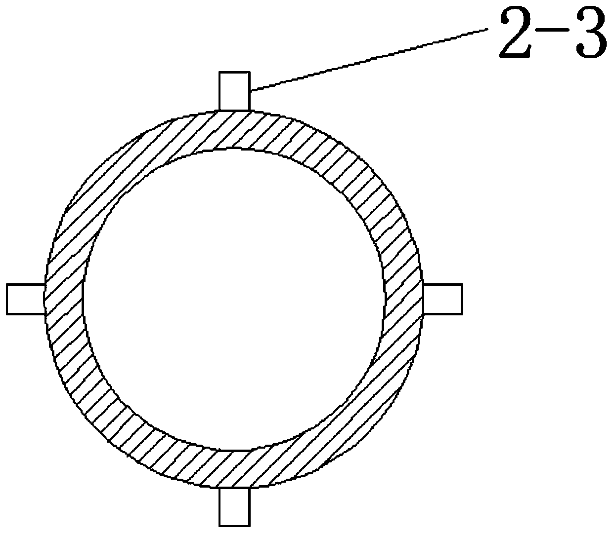
[0025] Embodiment 1: The thrombolytic removal device of this embodiment includes an outer tube 1, a transmission tube 2, a suction plug head 3, a plurality of thrombus breaking knives 4, a liquid cavity bag 5, a guide wire 6, a sliding seat 7, a driver 12, a negative Press the suction device 13 and the injector 14, the front end of the transmission tube 2 is provided with a fixed knife seat 2-1, and the tube body of the transmission tube 2 adjacent to the fixed knife seat 2-1 is provided with a plurality of through holes 2-2. The bolt head 3 is installed on the fixed knife seat 2-1 and is rotationally connected with the fixed knife seat 2-1. The transmission tube 2 is sleeved in the outer tube 1. One end of the transmission tube 2 with the through hole 2-2 extends out of the outer tube 1. The front end of the outer tube 1 is provided with a retaining edge 1-1, the inner wall of the outer tube 1 is provided with a retaining ring 1-2, and the outer wall of the outer pipe 1 betwee...

Embodiment 2

[0028] Embodiment 2: The method of using the thrombolytic thrombolytic removal device in this embodiment is realized according to the following steps:

[0029] 1. For blood vessel puncture, one end of the guide wire 6 penetrates into the blood vessel and passes through the thrombus, and the thrombolytic removal device is sent to the thrombus of the blood vessel along the other end of the guide wire 6;

[0030] 2. Inject the pressurized thrombolytic drug into the injection chamber 8 through the drug injector 14, and the pressurized thrombolytic drug pushes the sliding seat 7 forward through the axial through hole 1-3 on the stop ring 1-2, The thrombus breaking knife 4 is tensioned, the driver 12 drives the transmission tube 2 to rotate at a high speed, the transmission tube 2 drives the thrombus breaking knife 4 on the sliding seat 7 to rotate and chop the thrombus, and the thrombolytic drug pressurized in the liquid sac chamber 9 flows from the injection hole 5- 1. The thrombu...


PUM


Abstract

The invention provides a thrombus thrombolysis and clearing device and a use method thereof, and relates to the technical field of a medical appliance. The invention aims at solving the problems thatan existing thrombus clearing device is difficult to clear the thrombus on the vascular wall, so that the thrombus clearing is unthorough. A thrombus suction head in the thrombus thrombolysis and clearing device provided by the invention is arranged on a fixed cutter holder and is rotationally connected with the fixed cutter holder; a transmission tube is arranged in an outer tube in a sleeved way; the end, provided with a through hole, of the transmission tube extends out of the outer tube; a liquid cavity bag is arranged on the outer tube wall of the outer tube between a baffle edge and a baffle ring; a sliding seat is arranged on the transmission tube in a sleeving way and is glidingly connected with the transmission tube; the sliding seat is positioned between the baffle edge and the baffle ring; and a thrombus breaking cutter is fixedly arranged between the fixed cutter holder and the sliding seat. According to the thrombus thrombolysis and clearing device, pressurized normal saline or thrombolysis medicine is sprayed out from the liquid cavity bag to break the thrombus; meanwhile, a driver drives the transmission tube to rotate at a high speed; the thrombus breaking cutter onthe sliding seat is driven to perform rotary cutting on the thrombus; and the tensioned thrombus breaking cutter can scrape away the thrombus on the vascular wall. The thrombus thrombolysis and clearing device and the use method provided by the invention are applied to the field of medical care.

Description

technical field [0001] The invention belongs to the field of medical devices, and in particular relates to a thrombus-thrombosis removal device and a usage method thereof. Background technique [0002] At present, thrombus removal devices are widely used in clinical practice. Such devices generally remove thrombus in blood vessels by dissolving, crushing or aspiration, so as to restore blood circulation. However, the existing thrombus removal device is generally provided with a rotating blade inside the suction plug tube, and the thrombus is sucked into the suction plug tube by negative pressure suction, crushed by the rotating blade and pulled out of the body. After peeling off by negative pressure suction, it will still remain on the vessel wall, resulting in incomplete removal of thrombus, which will develop into thrombus and block the vessel again. Contents of the invention [0003] The purpose of the present invention is to solve the problem that the existing thrombu...

Claims


Application Information

Patent Timeline
IPC IPC(8): A61B17/22
CPCA61B17/22A61B2017/22079A61B2017/22084
Inventor 刘思宁田学峰杨颂
Owner 黑龙江省医院
Why Eureka
Try Eureka