
Wood product machining equipment

A technology of processing equipment and wood products, which is applied in the direction of wood processing equipment, manufacturing tools, and thin wood chip manufacturing, etc., can solve the problems of round wood waste, round wood damage, and round wood surface damage, etc. Effect of waste and ensuring surface quality

Active Publication Date: 2020-08-25
浙江景宁华寅工艺品有限公司
View PDF10 Cites 2 Cited by
  • Summary
  • Abstract
  • Description
  • Claims
  • Application Information

AI Technical Summary

Problems solved by technology

During the rotary cutting process, the log must always be clamped and squeezed and rotated in the effective position between the three rotating rollers to achieve rotary cutting. Closer, the gap between the three rollers decreases, and finally the blade cannot touch the log, resulting in a lot of waste of logs. At the same time, when the three rollers drive the log to rotate, in order to increase the friction with the log, three There are more convex parts on the first roller, which will cause excessive extrusion on the log, resulting in damage to the log, damage to the veneer that has been rotary cut, affecting the quality of the veneer, and reducing the impact of the three rollers on the log. Squeeze will cause the log to slide between the three rollers, and the convex part on the roller will cause scratches on the surface of the log, which will affect the overall processing efficiency of the log and at the same time cause damage to the surface of the log

Method used


Image

  • Wood product machining equipment
  • Wood product machining equipment
  • Wood product machining equipment

Examples


Embodiment Construction

[0018] In order to enable those skilled in the art to better understand the solutions of the present invention, the technical solutions in the embodiments of the present invention will be described clearly and completely in conjunction with the accompanying drawings in the embodiments of the present invention. Obviously, the described embodiments are only It is a part of the embodiments of the present invention, but not all the embodiments. Based on the embodiments of the present invention, all other embodiments obtained by those of ordinary skill in the art without creative work shall fall within the protection scope of the present invention.

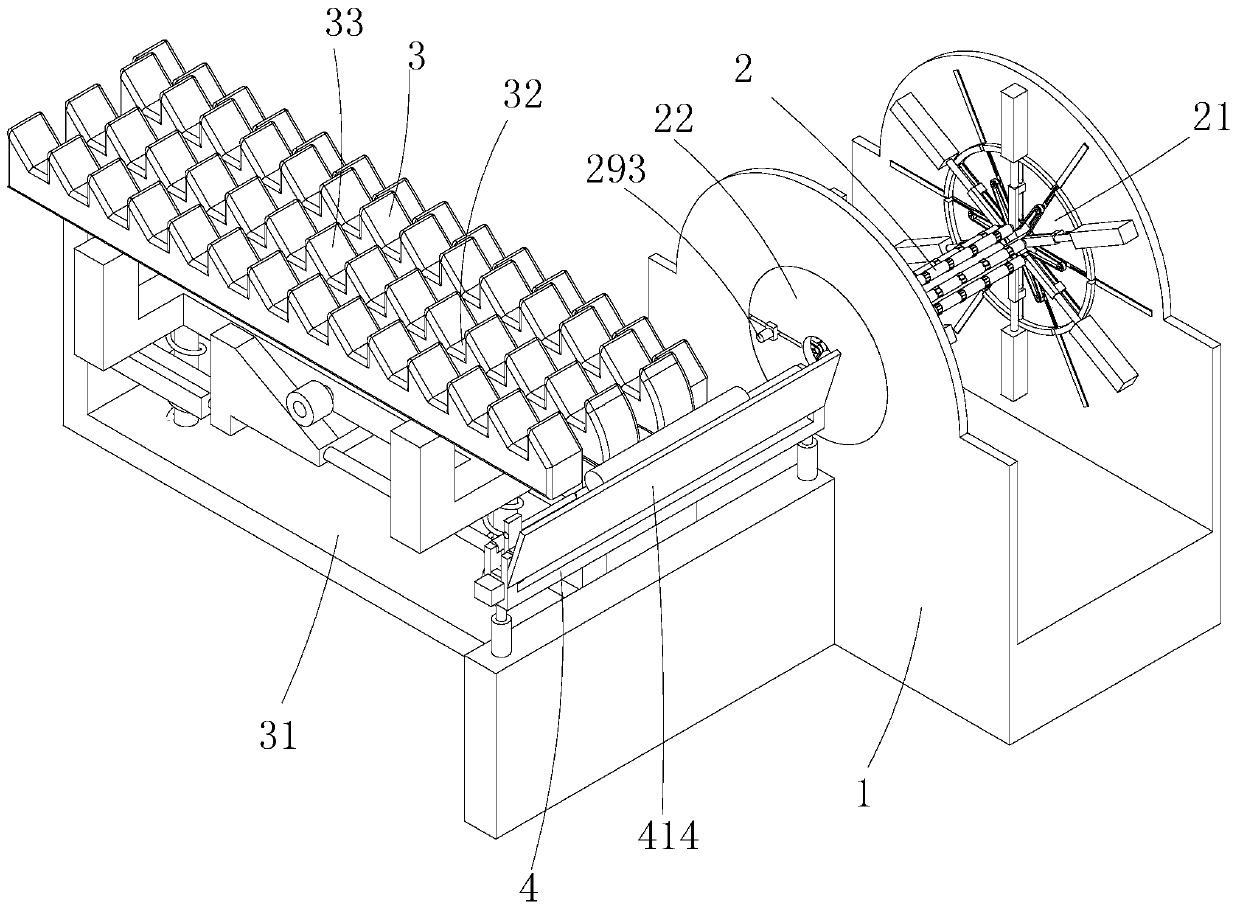
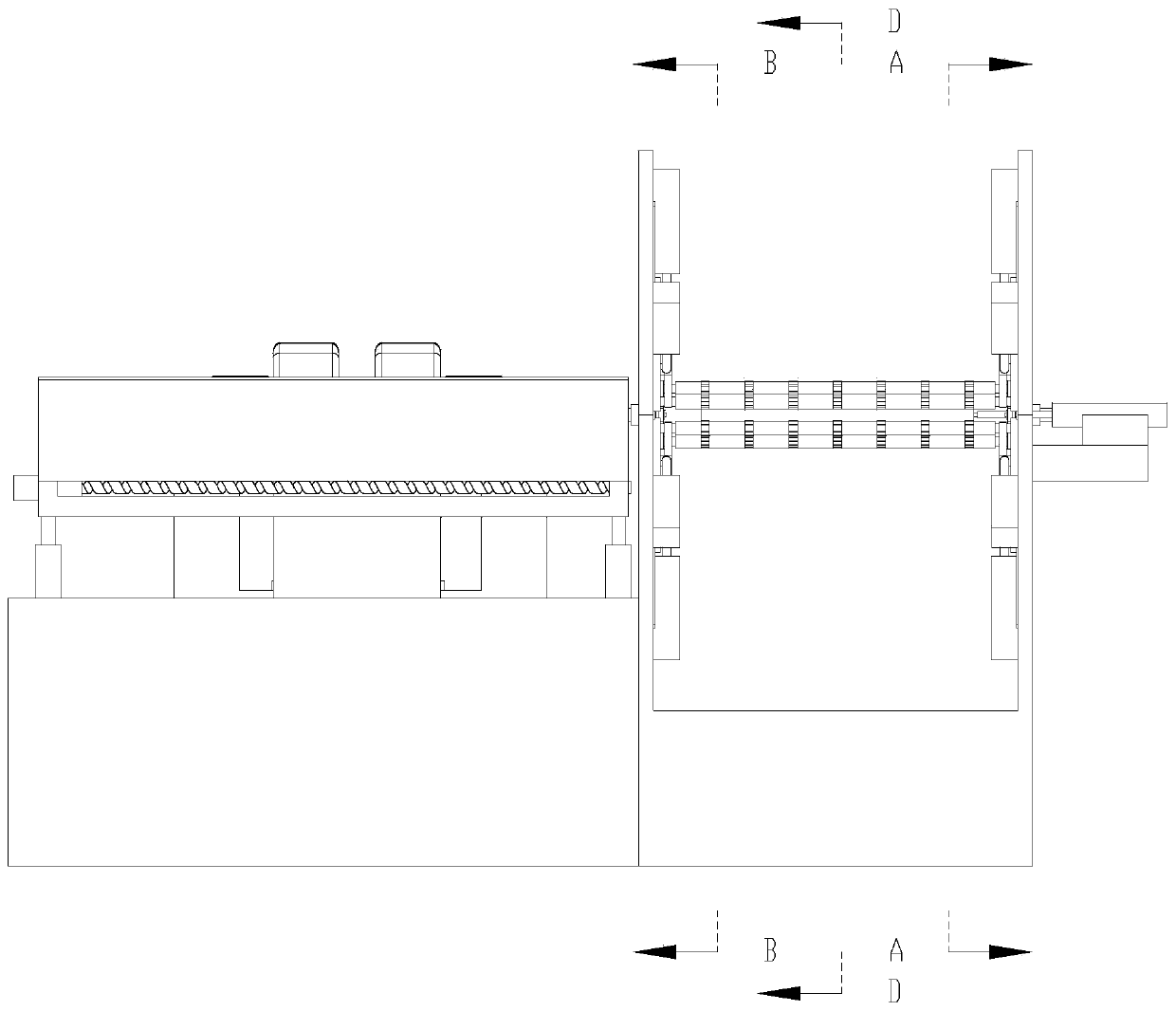
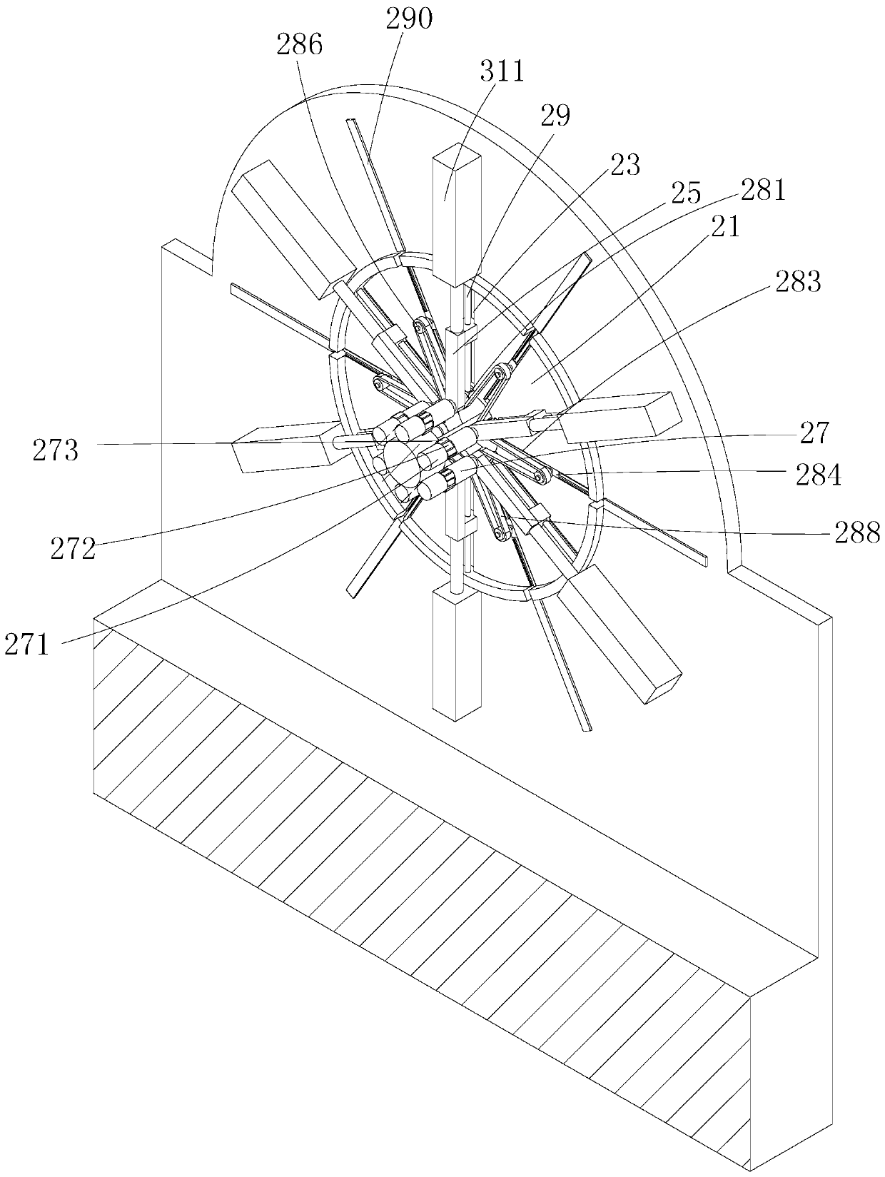
[0019] Such as Figure 1-8 As shown, a wood product processing equipment includes a body 1, a transmission device arranged on the body for rotating the log 2, a conveying device used for log transportation 3, and a pushing device arranged on both ends of the transmission device 4. The transmission device 2 includes a first base 21 fixedl...


PUM


Abstract

The invention discloses wood product machining equipment. The wood product machining equipment comprises a machine body, a transmission device arranged on the machine body and used for rotating logs,a conveying device used for conveying the logs and pushing devices arranged at the two ends of the transmission device, wherein the transmission device comprises a first base, a second base, a plurality of first sliding grooves annularly distributed in the first base at equal intervals, a plurality of second sliding grooves annularly distributed in the second base at equal intervals, a plurality of first sliding bases movably arranged on the plurality of first sliding grooves respectively, a plurality of second sliding bases movably arranged on the plurality of second sliding grooves respectively, a plurality of driving rollers with the two ends rotationally arranged on the plurality of first sliding bases and the plurality of second sliding bases correspondingly, a driving assembly for driving the plurality of driving rollers to rotate in the same direction, a plurality of first hydraulic cylinders for driving the plurality of first sliding bases to move and a plurality of second hydraulic cylinders for driving the second sliding bases to move. According to the wood product machining equipment, waste of the logs can be greatly reduced, and the rotating efficiency of the logs and the surface quality of veneers obtained after rotary cutting are ensured.

Description

Technical field [0001] The invention relates to the technical field of wood products, in particular to a wood product processing equipment. Background technique [0002] Due to the different diameters of raw logs, the feed inlet of the existing shaftless rotary cutting machine is generally designed according to the requirements of the largest diameter round wood, so as to adapt to the large and small diameter round wood can be peeled; this kind of rotary cutting The machine is handy when cutting large-diameter logs, but it is not so smooth for small-diameter logs. The reason is that the rotary cutting work of the shaftless rotary cutting machine is driven by three rotating rollers with constant linear speed to be cut to the circle. The wood is rotated for rotary cutting. The three rollers are the squeeze roller on the movable knife frame and the upper and lower main rollers on the rotary cutter frame; when the three rollers that clamp the log start to rotate After that, the mova...

Claims


Application Information

Patent Timeline
IPC IPC(8): B27L5/00B27L5/02B27C5/08
CPCB27C5/08B27L5/002B27L5/02B27L5/022
Inventor 周杰耘朱慧芬
Owner 浙江景宁华寅工艺品有限公司
Learn More