Sludge dewatering system

A sludge dewatering and rotor technology, which is used in water/sludge/sewage treatment, sludge treatment, dehydration/drying/concentrated sludge treatment, etc. Continuous dewatering and other problems to achieve the effect of improving sludge dewatering efficiency, avoiding secondary mixing, and realizing continuous dewatering operations

Inactive Publication Date: 2020-08-25
安徽清蓝环保工程有限公司
View PDF0 Cites 2 Cited by
  • Summary
  • Abstract
  • Description
  • Claims
  • Application Information

AI Technical Summary

Problems solved by technology

[0002] Traditional sludge dewatering generally uses a plate-and-frame filter press, but the plate-and-frame filter press cannot achieve continuous sludge dehydration, and the plate-and-frame filter press has a long single pressing cycle, and the unloading process is cumbersome. Cleaning and maintenance are time-consuming and laborious, and the operation efficiency is low

Method used


Image

  • Sludge dewatering system
  • Sludge dewatering system
  • Sludge dewatering system

Examples


Embodiment 1

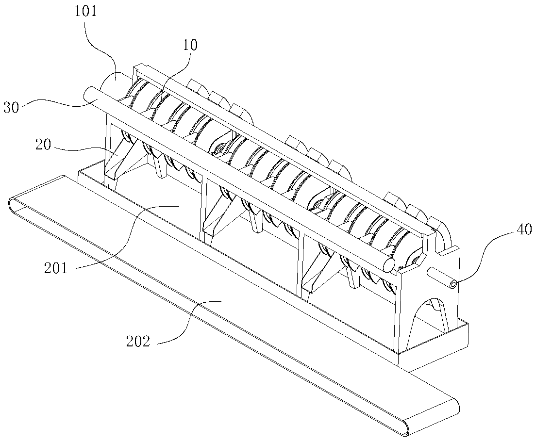
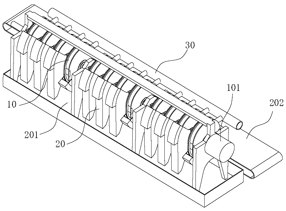
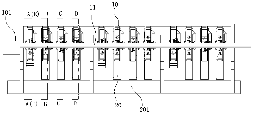
[0035] Such as figure 1 , 2 , 3, a sludge dewatering system includes a feed pipe 30, a dehydration mechanism 10, a liquid discharge pipeline 40 and a slag discharge device 20, the feed pipe 30 communicates with the feed port of the dewatering mechanism 10, and the dehydration mechanism 10 For squeezing sludge, the liquid discharge pipeline 40 communicates with the liquid discharge hole of the dewatering mechanism 10, and the slag discharge device 20 is located at the slag discharge port of the dewatering mechanism 10 and collects the dehydrated sludge; Figure 4 , 5 , 6, 7, 8, and 9, the dehydration mechanism 10 includes a rotor actuator, and the rotor actuator includes a main shaft 11, a rotor 13 and a housing 12, and the housing 12 includes two parallel end plates and connects two The side plate of the end plate, the side plate is a racetrack structure enclosed by two opposite semicircular walls and two opposite straight walls, the main shaft 11 runs through the housing 12 i...

Embodiment 2

[0045]A sludge dewatering method adopting the system described in embodiment 1 to process sludge comprises the steps:

[0046] Step 1: adding flocculant to the sludge to condition the sludge;

[0047] Step 2: Use the sludge pump to send the prepared sludge into the sludge dewatering system for dehydration;

[0048] Step 3: respectively recycle the wastewater discharged from the liquid phase outlet and the sludge discharged from the solid phase outlet of the sludge dewatering system.


PUM


Abstract

The invention belongs to the technical field of sludge treatment and specifically relates to a sludge dewatering system. The sludge dewatering system comprises a feeding pipe, a dewatering mechanism,a liquid discharging pipeline and a slag discharging device, wherein the feeding pipe communicates with a feeding port of the dewatering mechanism, the dewatering mechanism is used for squeezing sludge, the liquid discharging pipeline communicates with a liquid discharging hole of the dewatering mechanism, and the slag discharging device is located at a slag discharging port of the dewatering mechanism and collects dewatered sludge. Continuous extrusion of sludge in a shell is achieved through revolution and rotation of an arc triangle, so continuous dehydration operation of the sludge is achieved, and the dehydration efficiency of the sludge is improved. The slag discharging device is arranged to be of a movable structure, a material guiding groove moves to a position below the slag discharging hole and is used for guiding sludge to fall towards a conveying belt during slag discharging; and when slag discharging is not conducted, the material guiding groove is removed from the position below the slag discharging hole, and overflowing water drips into a water receiving groove, so secondary mixing of the overflowing water, water and the sludge is effectively avoided.

Description

technical field [0001] The invention belongs to the technical field of sludge treatment, and in particular relates to a sludge dewatering system. Background technique [0002] Traditional sludge dewatering generally uses a plate-and-frame filter press, but the plate-and-frame filter press cannot achieve continuous sludge dehydration, and the plate-and-frame filter press has a long single pressing cycle, and the unloading process is cumbersome. Cleaning and maintenance are time-consuming and laborious, and the operation efficiency is low. Contents of the invention [0003] The object of the present invention is to provide a sludge dewatering system capable of realizing continuous sludge dewatering. [0004] The technical scheme that the present invention takes is specifically as follows: [0005] A sludge dewatering system, comprising a feed pipe, a dehydration mechanism, a liquid discharge pipeline and a slag discharge device, the feed pipe communicates with the feed inl...

Claims


Application Information

Patent Timeline
Patent Type & Authority Applications(China)
IPC IPC(8): C02F11/122C02F11/14
CPCC02F11/122C02F11/14
Inventor 钟灵胡遵琪赵晓东
Owner 安徽清蓝环保工程有限公司
Why Eureka
Try Eureka