
High-efficient textile printing and dyeing device

A textile and high-efficiency technology, applied in the field of high-efficiency textile printing and dyeing devices, can solve the problems of prone to wrinkles, single textile styles, and failure of textile printing and dyeing, and achieve the effect of reducing wrinkles

Inactive Publication Date: 2020-08-25
蔚春
View PDF0 Cites 0 Cited by
  • Summary
  • Abstract
  • Description
  • Claims
  • Application Information

AI Technical Summary

Problems solved by technology

[0002] In the past, textiles were dyed directly in large dyeing vats, which made the styles of textiles single. With the improvement of people's living standards, there are more and more demands for textile dyeing patterns, and people have introduced efficient printing and dyeing equipment. However, the printing and dyeing devices on the market are all connected to the transmission shaft by connecting the textile to the transmission shaft, and the transmission is carried out by rotating the transmission shaft at different height positions. Wrinkles are easy to appear during the transmission process. When the textile has wrinkles, the printing and dyeing device will print out the folds during the printing and dyeing process, which will cause confusion in the printing and dyeing of the textile fabric.

Method used

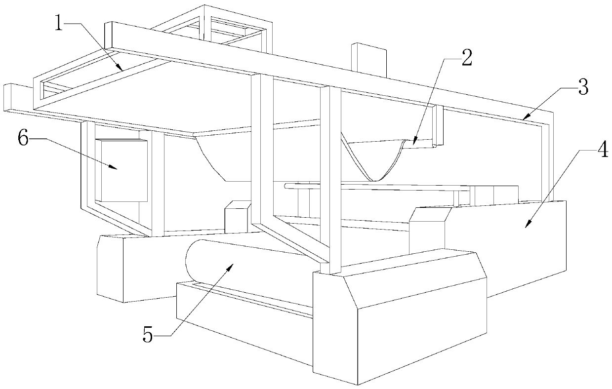

Image

  • High-efficient textile printing and dyeing device
  • High-efficient textile printing and dyeing device
  • High-efficient textile printing and dyeing device

Examples


Embodiment 1

[0028] see Figure 1-Figure 5 , a high-efficiency printing and dyeing device for textiles. The present invention provides a high-efficiency textile printing and dyeing device, the structure of which includes a processor 1, a pole wheel 2, a bracket 3, a body 4, a roller 5, and a control box 6. The upper part of the body 4 is connected to the The processor 1 is mechanically connected, the body 4 is fixedly connected with the support 3, the rear of the processor 1 is provided with a pole wheel 2, the left side of the body 4 is equipped with a control box 6, and the roller 5 is connected to the body 4 Actively connected through the connection axis;

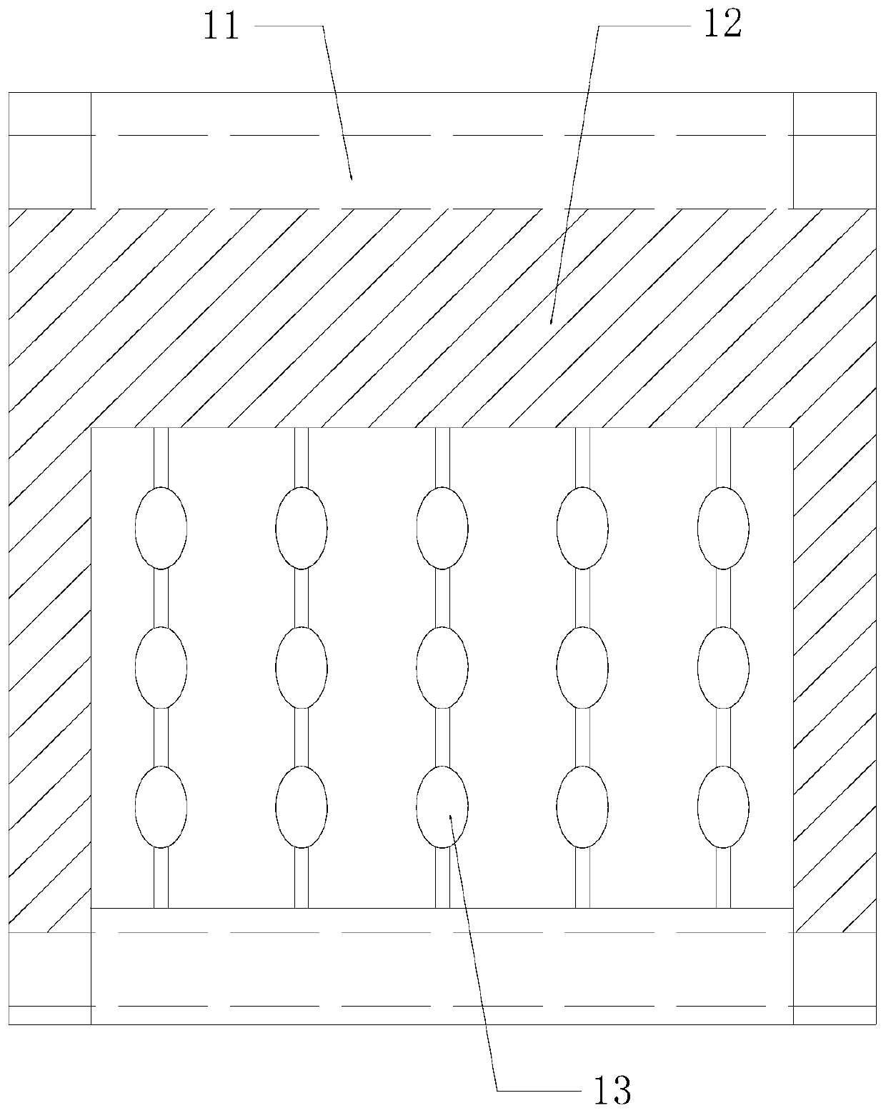
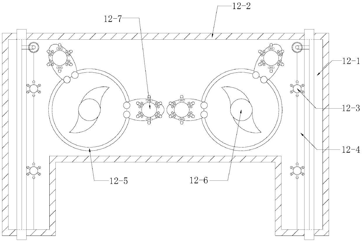
[0029] The processor 1 is composed of a transmission body 11, a smoother 12, and a rotating bead 13. The transmission body 11 is mechanically connected with the smoother 12, and the rotating bead 13 is movably connected with the transmission body 11 through a movable shaft. The conveying body 11 is installed above the machine body 4...

Embodiment 2

[0036] see Figure 1-Figure 7 , a high-efficiency printing and dyeing device for textiles. The present invention provides a high-efficiency textile printing and dyeing device, the structure of which includes a processor 1, a pole wheel 2, a bracket 3, a body 4, a roller 5, and a control box 6. The upper part of the body 4 is connected to the The processor 1 is mechanically connected, the body 4 is fixedly connected with the support 3, the rear of the processor 1 is provided with a pole wheel 2, the left side of the body 4 is equipped with a control box 6, and the roller 5 is connected to the body 4 Actively connected through the connection axis;

[0037] The processor 1 is composed of a transmission body 11, a smoother 12, and a rotating bead 13. The transmission body 11 is mechanically connected with the smoother 12, and the rotating bead 13 is movably connected with the transmission body 11 through a movable shaft. The conveying body 11 is installed above the machine body 4...


PUM


Abstract

The invention discloses a high-efficient textile printing and dyeing device which structurally comprises a processor, a support rod wheel, a support, a machine body, a rolling wheel and a control cabinet. The upper part of the machine body is mechanically connected with the processor; the machine body is fixedly connected with the support; the support rod wheel is arranged in the rear of the processor; the control cabinet is arranged on the left side of the machine body; and the rolling wheel is movably connected with the machine body through a connecting shaft. According to the high-efficienttextile printing and dyeing device provided by the invention, a textile is clamped through a clamping body, and a bulge block is arranged on a camber surface of a clamping block of the clamping bodyso as to increase a friction force, so that the textile is not easy to fall off when being clamped; and when the textile is clamped onto a pulley and is loosened, the surface of the clamping block cansweep the textile on the edge so as to flatten wrinkles on the edge, and under the clamping of a turnover block, the textile is conveyed through the pulley after two sides of the textile are clamped,so that on one hand, a mini conveying function is realized, and on the other hand, the wrinkles of the textile can be greatly reduced since the two sides are straightened by tensile forces.

Description

technical field [0001] The invention relates to the field of textiles, in particular to a high-efficiency printing and dyeing device for textiles. Background technique [0002] In the past, textiles were dyed directly in large dyeing vats, which made the styles of textiles single. With the improvement of people's living standards, there are more and more demands for textile dyeing patterns, and people have introduced efficient printing and dyeing equipment. However, the printing and dyeing devices on the market are all connected to the transmission shaft by connecting the textile to the transmission shaft, and the transmission is carried out by rotating the transmission shaft at different height positions. Wrinkles are easy to appear during the transmission process. When the textile has wrinkles, the printing and dyeing device will print out the folds during the printing and dyeing process, which will cause confusion in the printing and dyeing of the textile fabric. Conten...

Claims


Application Information

Patent Timeline
Patent Type & Authority Applications(China)
IPC IPC(8): D06C15/00D06G1/00
CPCD06C15/00D06G1/00
Inventor 蔚春
Owner 蔚春
Learn More