
Double-row pile supporting structure

A technology of supporting structure and double-row piles, which can be used in infrastructure engineering, coastline protection, excavation, etc., can solve the problems of weak bending resistance and limited effect of single-row piles

Pending Publication Date: 2020-08-25
CHINA SOUTHWEST ARCHITECTURAL DESIGN & RES INST CORP LTD
View PDF0 Cites 2 Cited by
  • Summary
  • Abstract
  • Description
  • Claims
  • Application Information

AI Technical Summary

Problems solved by technology

[0003] The purpose of the present invention is to provide a method that can enhance the lateral stiffness of double-row piles and strengthen the structural support system in view of the above-mentioned problems of limited spatial effect of the existing double-row pile system and weak bending resistance of single-row piles Bending capacity of double-row pile support structure

Method used


Image

  • Double-row pile supporting structure
  • Double-row pile supporting structure
  • Double-row pile supporting structure

Examples


specific Embodiment 1

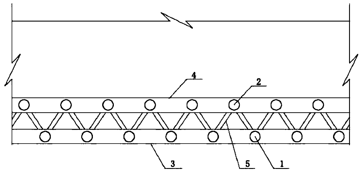
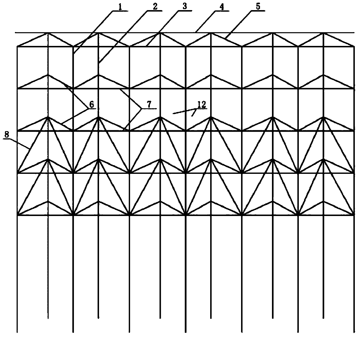
[0036] A double-row pile support structure, which is used in the slope support and is a permanent structure. The pile diameter of the front row is 800mm, and the pile diameter of the back row is 800mm. The reinforced concrete pouring pile is constructed by mechanical hole forming , arranged in double rows of equilateral triangles, with a spacing of 2m. Several groups of steel bars are reserved for the front row of pile webs. Each group has 10 steel bars with a diameter of 22mm, which are used to connect the front row of web bars. Each group has 10 pieces with a diameter of 22mm. The diameter of the steel bars reserved for the front row of pile reinforcement mesh is 10mm and the vertical spacing is 150mm. There are several sets of steel bars reserved for the back row of pile web bars in the rear row of piles. The steel bars are 10 for each group. The root diameter is 22mm, and the diameter of the steel bars reserved for the rear row of reinforcement mesh is 10mm and the vertical...

specific Embodiment 2

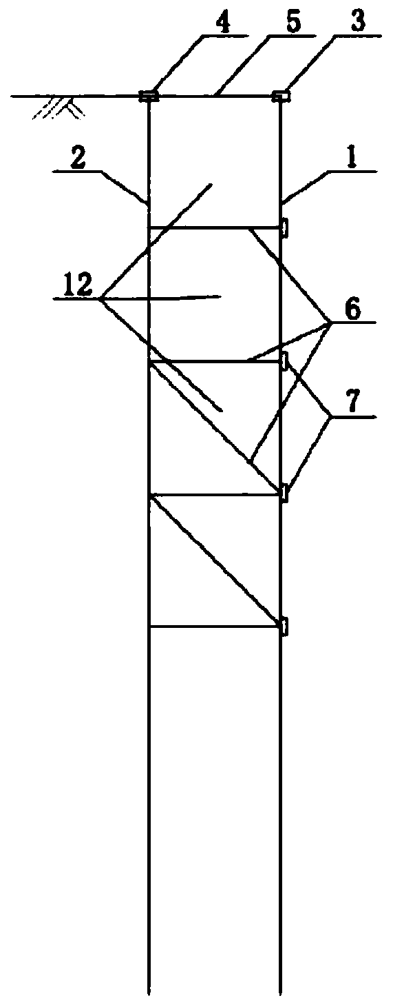
[0039] A double-row pile support structure is different from Embodiment 1 in that the use scenario is temporary foundation pit support. The front row of piles and the rear row of piles are made of steel pipe piles, the diameter of which is 500mm, and the vibro-pile method is adopted. The double rows of equilateral triangles are arranged with a distance of 1.5m. Bolt holes are reserved for the pile body of the front row, and bolt holes are reserved for the pile body of the rear row. The top of the front row of piles is equipped with double 300mm I-steel front crown beams and front connecting plates, and the rear pile top is equipped with double 300mm I-steel rear crown beams and rear connecting plates. Connecting plates and bolts connect the front row of piles and the rear row of piles.

[0040] Then carry out excavation in layers and grades of the foundation pit, and every layer of high 500mm excavation installs a V-shaped soil retaining plate, which is equivalent to the scre...


PUM


Abstract

The invention discloses a double-row pile supporting structure. The double-row pile supporting structure comprises front row piles and rear row piles, wherein front row crown beams are arranged at thetops of the front row piles, and rear row crown beams are arranged at the tops of the rear row piles; rigid-frame beams are arranged between the front row piles and the rear row piles; the front rowpiles, the rear row piles and the rigid-frame beams together form a plane truss structure; connecting web members vertically arranged at intervals are arranged between adjacent front row pile bodies and back row pile bodies; front row web members vertically arranged at intervals are arranged between adjacent pile bodies of the front row piles; and a spatial triangle truss column structure is formed between every two adjacent front row pile bodies and the corresponding rear row piles. According to the double-row pile supporting structure, the spatial triangle truss column structure supporting system with the pile bodies connected with the web members solves the existing problems of limited action effects of a dual-row pile spatial system and poor bending resistance of single-row piles, effective connection between the front row piles and the rear row piles is achieved, the space integrated structure is formed, lateral rigidity of the double-row piles is enhanced, and the bending resistance of the structure supporting system is improved.

Description

technical field [0001] The invention relates to the technical fields of municipal engineering, construction engineering and water conservancy engineering, in particular to a double-row pile support structure suitable for high slope support, deep foundation pit support and deep river embankment protection, which can be used as a temporary or permanent structure used. Background technique [0002] With the rapid development of national park city construction, there are more and more dangerous projects such as high slopes, deep foundation pits and high embankments, and the emphasis on safety issues has reached a new height. The double-row pile support structure is a relatively new type of support. The rigidity of the support structure is similar to that of the gantry structure. Although the function of the structure has been greatly improved compared with that of the single-row pile, the bending resistance is higher. The single-row piles have also been greatly improved, but th...

Claims


Application Information

Patent Timeline
Patent Type & Authority Applications(China)
IPC IPC(8): E02D17/20E02D17/04E02B3/06
CPCE02B3/066E02D17/04E02D17/207
Inventor 吴强吴勇文琪鑫刘超邵燕超
Owner CHINA SOUTHWEST ARCHITECTURAL DESIGN & RES INST CORP LTD
Learn More