

Dewatering and drainage structure of post-cast strip and construction method thereof
A drainage structure and construction method technology, applied in underwater structures, infrastructure engineering, water conservancy projects, etc., can solve the problems of slow drainage in the basement, easy blockage of drainage pipes, etc., to avoid drainage blockage, reduce construction drainage costs, Ensure smooth water seepage
- Summary
- Abstract
- Description
- Claims
- Application Information
AI Technical Summary
Problems solved by technology
Method used
Image

Examples
Embodiment 1
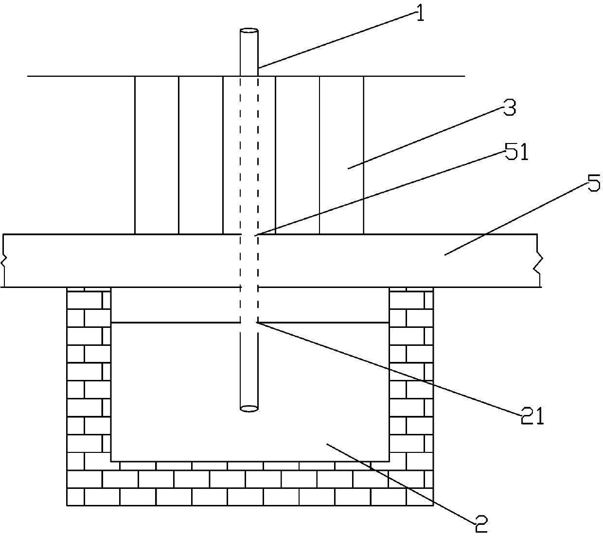
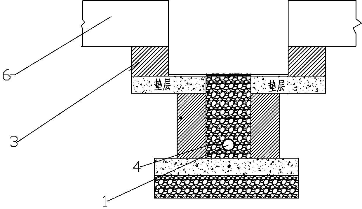
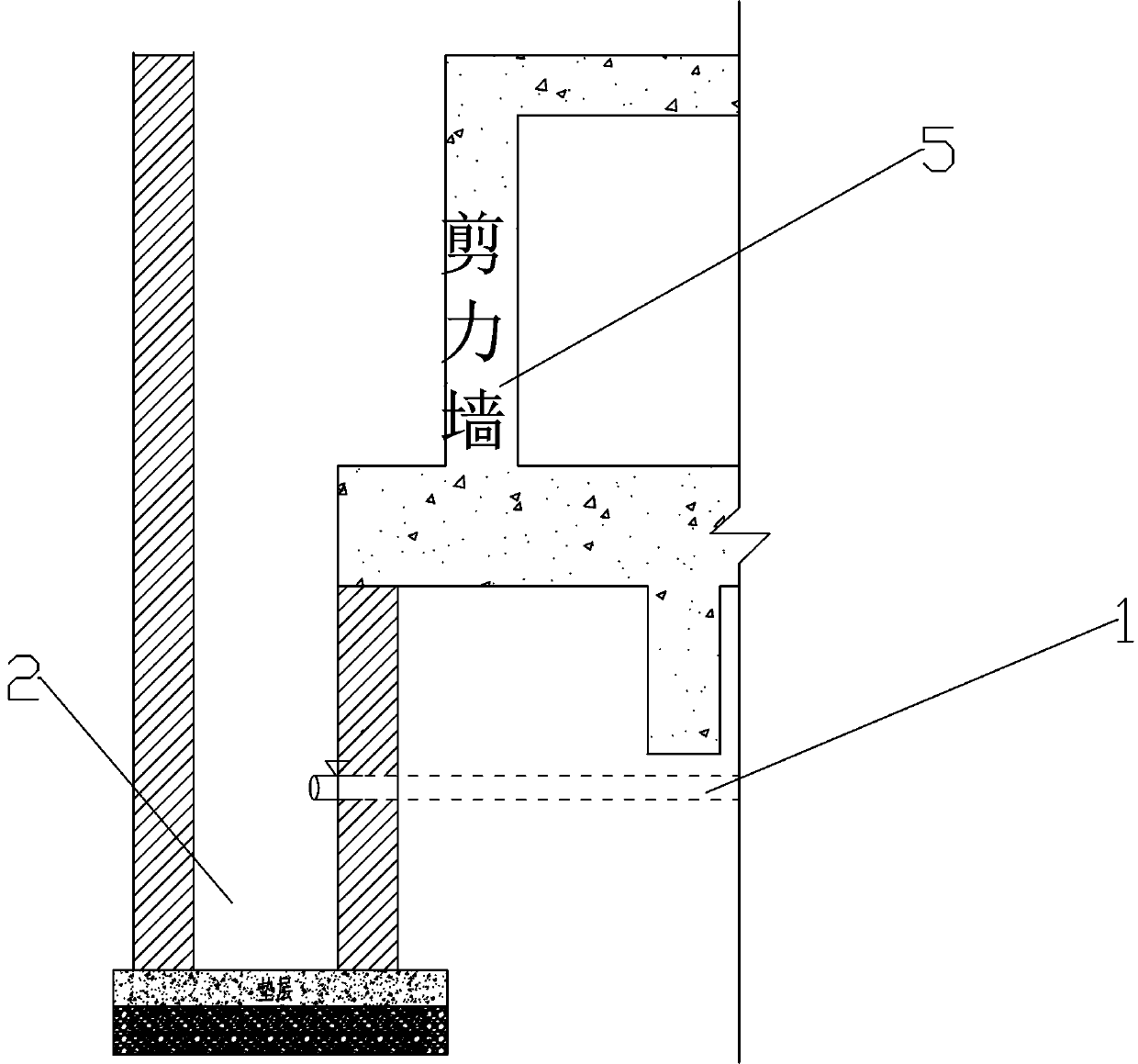
[0037] A post-casting belt drainage structure, including a drainage pipe 1 buried in the post-casting belt, a water collection well 2 connected to the drainage pipe 1, and a diversion part 3 distributed on the side of the post-casting belt. The drainage pipe The pipe wall of 1 is provided with non-uniformly distributed through-holes 11, the pipe body of the drainage pipe 1 is provided with a filter screen 4 for filtering, and the wall of the water collection well 2 is provided with a first connection for connecting the drainage pipe 1. Hole 21, groundwater or water collection first collects around the drainpipe 1 through the diversion part 3, then flows into the drainpipe 1 through the through hole 11 of the drainpipe 1, and then collects into the water collection well 2 to realize the drainage of the basement. The diversion part 3. It is beneficial to lead the water flow into the drainage pipe 1. The filter screen 4 effectively filters the sediment and debris to prevent the th...
Embodiment 2
[0045] A construction method for a post-pouring belt drainage structure, comprising the following steps:
[0046] S1. Concrete porous bricks are built on both sides of the post-pouring belt, and C15 concrete cushion is poured in the middle;
[0047] S2. Open non-uniformly distributed through holes 11 on the PVC pipe wall and cover the filter screen 4 outside the PVC pipe body as the drain pipe 1, and the diameter of the PVC pipe is 50mm;
[0048] S3. Laying the drainage pipe 1 on the upper surface of the C15 concrete cushion;
[0049] S4. lay gravel above the C15 concrete cushion to completely cover the drainage pipe 1;
[0050] S5. After dry laying the linoleum layer above the crushed stone, pour 30mm thick fine stone concrete on the crushed stone;
[0051] S6. Open the first communication hole 21 on the side wall of the water collection well 2 and communicate with the water collection well 2 and the drainpipe 1. In this program, the water collection well 2 can be a cylinde...
PUM
 Abstract
Description
Claims
Application Information