Sloping roof concealment type exit roof pipeline ventilation device and construction process

A technology for ventilation devices and sloping roofs, which is applied to roofs, roof coverings, building roofs, etc., can solve problems such as unreliable waterproof performance, difficult construction, and difficult waterproofing, so as to prevent inverted siphoning of rainwater, Elimination of leakage hazards and increased safety

Pending Publication Date: 2020-08-25
北京金鑫雅居工程技术有限公司
View PDF0 Cites 1 Cited by
  • Summary
  • Abstract
  • Description
  • Claims
  • Application Information

AI Technical Summary

Problems solved by technology

[0005] 1. The waterproofing between the pipe root and itself and the sloping roof is very difficult to deal with, and leakage often occurs;
[0006] 2. After leaving the roof, it is very difficult to close the joint with the roof tiles, resulting in a poor appearance; usually use mortar to close the joint, and then paint the same color as the tile, but the mortar closes, it is easy to pollute the tile surface, and it is easy to crack ;During construction, it is necessary to cut out circular holes on the roof tiles, which is difficult to construct, and the waterproof performance of the tile itself becomes unreliable;
At this time, the outer frame of the building construction has been removed, the construction is extremely dangerous, and it is easy to step on the roof tiles;
[0008] 4. In the later stage of water supply and drainage construction, if the seal between the roof pipe and the casing is not good, it will cause rainwater to leak into the room along the gap between the pipe and the casing;
[0009] 5. Due to the difficulty of waterproof construction here, the construction speed is very slow. It takes at least 2-3 hours for a skilled technician to do a complete waterproofing and closing treatment of the roof pipe; and the amount of materials is large

Method used


Image

  • Sloping roof concealment type exit roof pipeline ventilation device and construction process
  • Sloping roof concealment type exit roof pipeline ventilation device and construction process
  • Sloping roof concealment type exit roof pipeline ventilation device and construction process

Examples


Embodiment Construction

[0044] The specific implementation manners of the present invention will be described in further detail below in conjunction with the accompanying drawings.

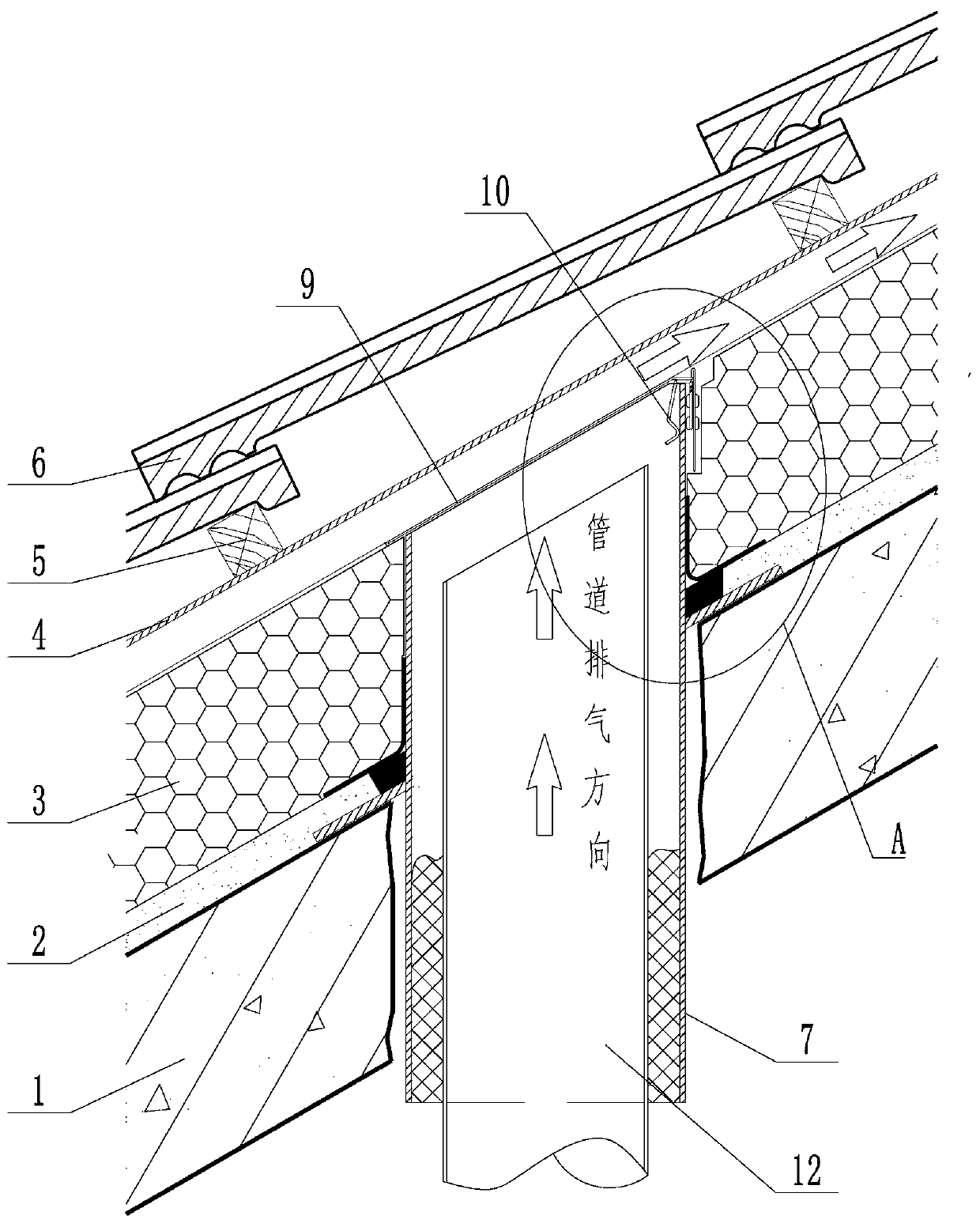
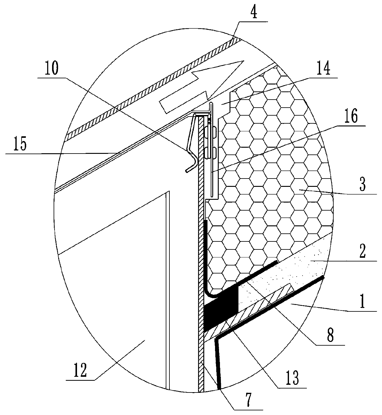
[0045] Depend on Figure 1 to Figure 8 It can be seen that the present invention takes the corrugated asphalt waterproof tile roof system as an example, and the construction method of the tile roof with ventilation interlayer constructed by other dry-hanging methods is the same.

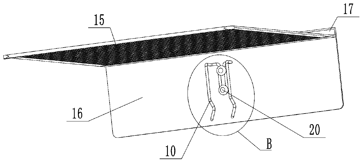
[0046] When carrying out construction, the present invention mainly includes new construction technology and supporting parts, and supporting parts are cover 9 and torsion spring 10, and structure is as Figure 4-7 As shown, the cover plate 15 can be bent arbitrarily, and is suitable for tile roofs with all slopes. The structures at different angles are as follows Figure 8 shown.

[0047] A concealed ventilating device for ventilating pipes on a sloping roof. The sloping roof consists of a roof panel 1, a leveling layer 2, an insulation laye...


PUM


Abstract

The invention provides a sloping roof concealment type exit roof pipeline ventilation device. The sloping roof concealment type exit roof pipeline ventilation device comprises a sleeve, the sleeve runs through a roof plate, a leveling layer and a heat preservation layer, the upper end of the sleeve is flush with the heat preservation layer, an upper-end pipe mouth of the sleeve is cut slantly, thesleeve is wound by butyl tape and is in seal connection with the leveling layer, the upper end of the sleeve is detachably and fixedly provided with a seal cover, the seal cover is fixed to the upperside of an inclined plane of the sleeve through a torsional spring, the size of the seal cover is larger than that of the sleeve, the seal cover is evenly distributed with a plurality of ventilationholes, and the sleeve is internally connected with an exit roof pipe in a sleeving manner. Compared with the prior art, by means of the sloping roof concealment type exit roof pipeline ventilation device, the construction difficulty is greatly reduced, roof tiles are not damaged, the water resistance is more reliable, and structures are more stable.

Description

technical field [0001] The invention relates to the technical field of building construction, in particular to a concealed ventilating device for a roof-exiting pipe on a sloping roof and a construction process. Background technique [0002] As the main component of the water supply and drainage system of the building, the main drainage pipe of the bathroom and kitchen, this device is essential. The main drainage pipe of the flat roof must protrude no less than 300mm from the roof in order to discharge the turbid air in the pipe and balance the pressure of the pipe. The main reason why flat roof pipes need to protrude out of the roof is that there is no ventilation interlayer on the flat roof, so they can only protrude out of the roof; even if there is an insulation layer, they cannot be effectively discharged to the outside. Second, because the flat roof needs to be occupied by people, the emission of foul air must be higher than the height of the human body. [0003] The...

Claims


Application Information

Patent Timeline
Patent Type & Authority Applications(China)
IPC IPC(8): E04D11/02E04D13/143E04D13/16
CPCE04D11/02E04D13/143E04D13/1693
Inventor 米星刘建国司书坚朱巍李伟王达宋连亮刘海军王宇金增华王建丰刘栋李俊中聂雷
Owner 北京金鑫雅居工程技术有限公司
Why Eureka
Try Eureka