Shock valve, slewing hydraulic system and crane
A buffer valve and hydraulic oil technology, applied in the field of hydraulic components, can solve problems such as difficulty, poor effect, and poor effect
- Summary
- Abstract
- Description
- Claims
- Application Information
AI Technical Summary
Problems solved by technology
Method used
Image
Examples
Embodiment approach
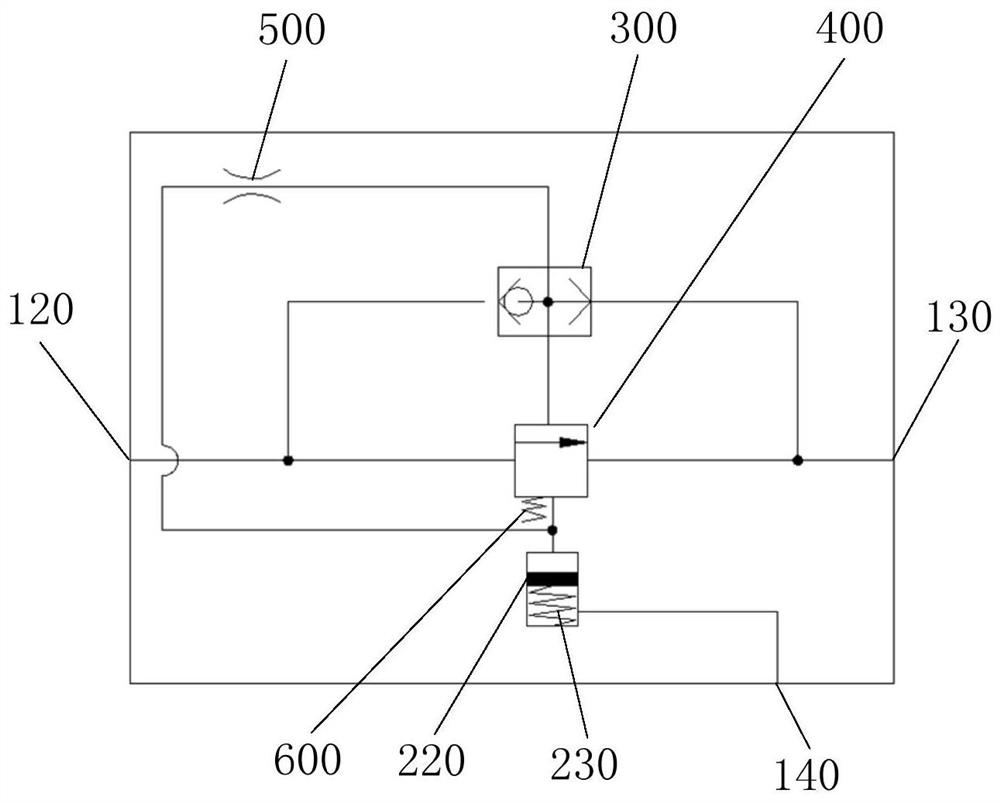
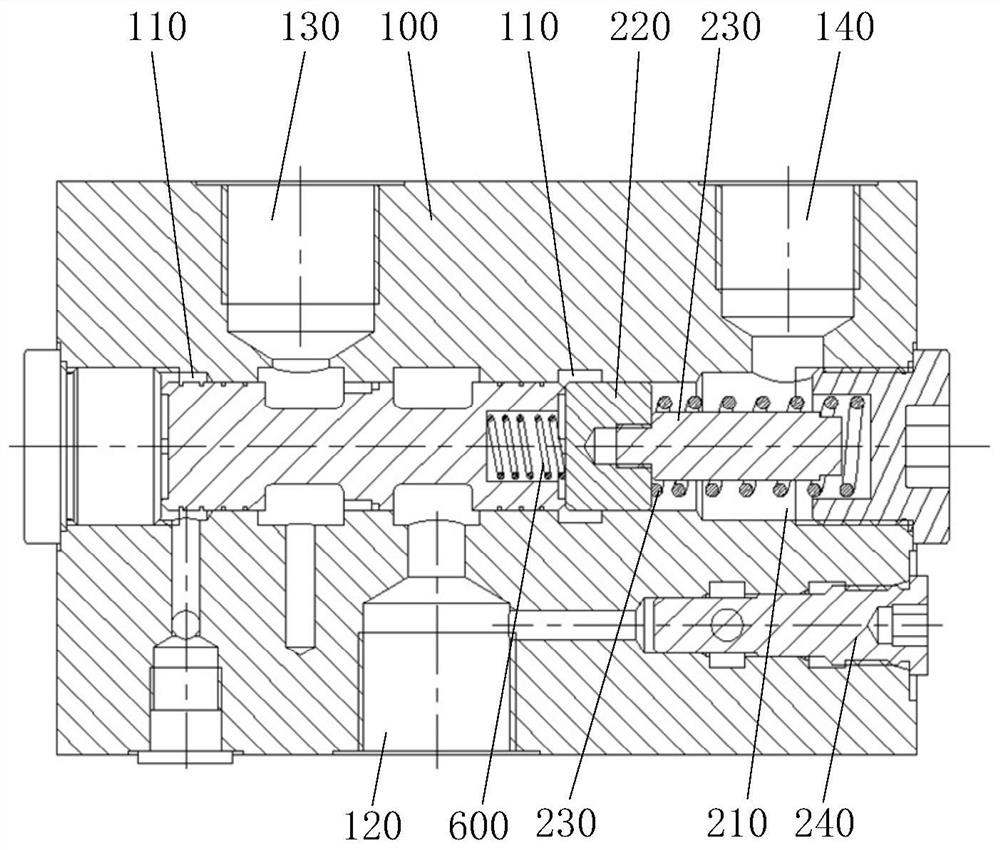
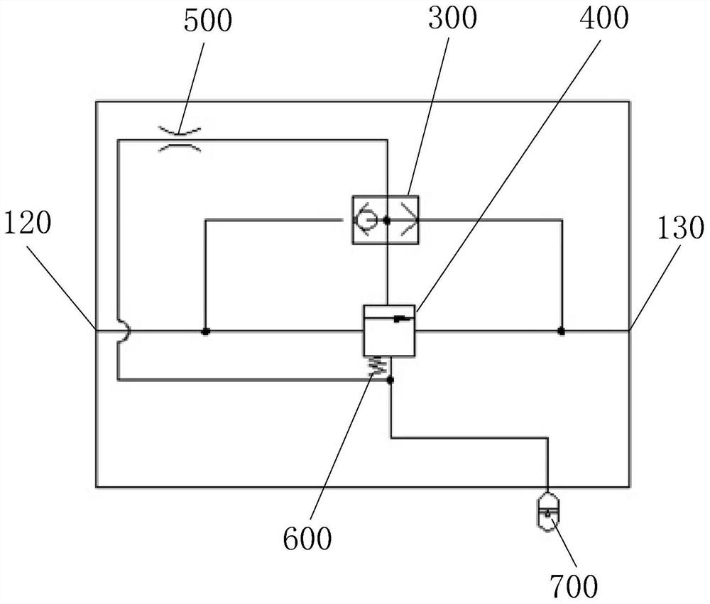
[0031] As an embodiment, the variable volume assembly includes a second chamber 210, a variable volume piston 220 and an elastic member. The second chamber 210 is provided in the buffer valve body 100 and communicates with the first chamber 110. The variable volume piston 220 and the elastic member The elastic members are all disposed in the second chamber 210 , and the elastic member is located on the side of the variable volume piston 220 away from the first chamber 110 , so that the variable volume piston 220 has a tendency to move closer to the first chamber 110 .
[0032] Specifically, the hydraulic oil flowing out from the shuttle valve 300 enters the left end of the first chamber 110 through the first oil path, and has a negative impact on the buffer valve core 400 figure 2 The shown left end face generates a force, and the original hydraulic oil on the right side of the buffer spool 400 pushes the variable volume piston 220 to move to the right and enters the second ch...
PUM
 Abstract
Description
Claims
Application Information
 - R&D
- Intellectual Property
- Life Sciences
- Materials
- Tech Scout
- Unparalleled Data Quality
- Higher Quality Content
- 60% Fewer Hallucinations
Browse by: Latest US Patents, China's latest patents, Technical Efficacy Thesaurus, Application Domain, Technology Topic, Popular Technical Reports.
© 2025 PatSnap. All rights reserved.Legal|Privacy policy|Modern Slavery Act Transparency Statement|Sitemap|About US| Contact US: help@patsnap.com


