Waste incineration device

A technology of waste incineration and incinerator, applied in the direction of incinerator, combustion type, combustion method, etc., can solve the problems of particulate dust cannot be captured and filtered, clogged filter, filter clogged, etc., to achieve ingenious structural design, compression process Smooth, anti-clogging effect

Active Publication Date: 2020-08-25
XIAN JUYUAN INFORMATION TECH CO LTD
View PDF12 Cites 2 Cited by
  • Summary
  • Abstract
  • Description
  • Claims
  • Application Information

AI Technical Summary

Problems solved by technology

At present, most of the incinerated dust is captured and collected by a filter in the filter room. However, when the garbage is incinerated, the smoke and dust are very large, and the dust after the incineration of the floating garbage needs to be initially separated and collected to improve the dust collection rate. Collect dust more fully
However, when the current garbage is incinerated to collect dust, due to too much dust, it is easy to block the filter screen when it enters the filter room at one time, especially when there are many types of garbage, covering comprehensive garbage from industry, life and other channels. The types of particulate dust contained are also widely distributed. Some difficult-to-filter flame-retardant dross must block the filter screen, and the particulate dust produced by other garbage incineration cannot be captured and filtered. Therefore, in this case, how to better filter and extracting the corresponding dust particles is also a challenge

Method used


Image

  • Waste incineration device
  • Waste incineration device
  • Waste incineration device

Examples


Embodiment Construction

[0012] The implementation of the present invention will be illustrated by specific specific examples below, and those skilled in the art can easily understand other advantages and effects of the present invention from the contents disclosed in this specification.

[0013] Below in conjunction with accompanying drawing and embodiment the present invention will be further described:

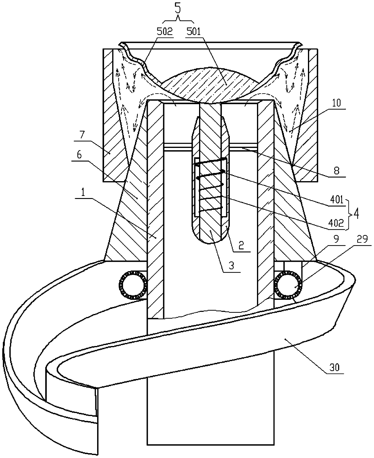
[0014] This embodiment provides a garbage incineration device, which mainly includes a pre-pressing device and a soot treatment device. The dry and compressed garbage is sent to the incinerator for burning, and the above-mentioned smoke treatment device is installed in the flue of the incinerator. Specifically, the soot treatment device such as figure 1As shown, it includes a vertically arranged smoke inlet pipe 1 connected to the flue. The smoke inlet pipe 1 is coaxially fixed with an installation shaft 2 at its outlet end. The installation shaft 2 can pass through the inside of the smoke inlet p...


PUM


Abstract

The invention discloses a waste incineration device which comprises a vertical smoke inlet pipe connected into a flue. An installing shaft is coaxially fixed into the position close to an outlet end of the smoke inlet pipe. A valve rod is axially and slidingly installed in the installing shaft. A dustproof cover on the valve rod comprises a gravity center body and a dust blocking cover ring whichare integrally connected. The gravity center body is fixedly connected with the valve rod. A pre-pressing device comprises an outer sleeve, an inner sleeve and a flow guide cover cylinder. The flow guide cover cylinder axially and slidingly sleeves the inner sleeve. A compression cylinder, a supporting rod, a bottom plate and a hydraulic supporting shaft are sequentially arranged in the inner sleeve from top to bottom. The hydraulic supporting shaft is used for supporting the bottom plate and pushing the bottom plate to move up and down. The bottom plate is connected with the compression cylinder through the supporting rod. A compression channel for compressing waste is formed in the compression cylinder. The waste incineration device can primarily collect dust obtained after comprehensivewaste incineration, lays a firm foundation for further thorough removal of dust, and can efficiently and smoothly compress and squeeze waste before incineration.

Description

technical field [0001] The invention belongs to the technical field of garbage treatment, in particular to a garbage incineration device. Background technique [0002] A lot of garbage is generated in daily production and life. One of the ways to deal with these garbage is to use traditional incineration. In order to recycle energy, existing garbage incineration is mostly used for power generation. When the current garbage is incinerated, the moisture content is too high, the garbage is fluffy, and the floor area is large, which is not convenient to transfer to the incinerator for centralized incineration. Some existing garbage compression devices do not compress the garbage enough, and it is difficult to take it out when the compression is sufficient. And transfer garbage, especially for continuous compression of garbage, the garbage will often be blocked in the compression channel, or the channel setting is unreasonable, resulting in insufficient compression. In addition,...

Claims


Application Information

Patent Timeline
Patent Type & Authority Applications(China)
IPC IPC(8): F23G5/02F23G5/033F23G5/04F23G5/44F23G5/48F23J3/00F23J15/02B08B3/02B08B13/00B08B15/02
CPCF23G5/02F23G5/04F23G5/033F23G5/444F23G5/48F23G5/44F23J15/022F23J3/00B08B3/02B08B15/02B08B13/00Y02E20/12
Inventor 不公告发明人
Owner XIAN JUYUAN INFORMATION TECH CO LTD
Why Eureka
Try Eureka