Visual test device and method for shear-seepage coupling failure process

A test device and percolation technology, applied in the direction of applying stable shear force to test material strength, measuring device, using applied stable tension/pressure to test material strength, etc., can solve the problem of low osmotic pressure, invisible shear box, The problem of poor sealing of the shear box is achieved to improve the sealing effect

Inactive Publication Date: 2020-08-25
SHANDONG UNIV OF SCI & TECH
View PDF0 Cites 5 Cited by
  • Summary
  • Abstract
  • Description
  • Claims
  • Application Information

AI Technical Summary

Problems solved by technology

[0004] The inventors found that the current common shear seepage test has poor sealing performance of the shear cell and can withstand low seepage pressure, so it can only realize the shear seepage test under the condition of low seepage pressure. It is impossible to carry out the test, and the inside of the common shear box is not visible at present. It is impossible to observe the specific failure process of the rock bridge during the shear-seepage coupling test, and only the final failure result can be obtained. The specific failure process under the coupled action of shear-seepage flow is very unfavorable.

Method used


Image

  • Visual test device and method for shear-seepage coupling failure process
  • Visual test device and method for shear-seepage coupling failure process
  • Visual test device and method for shear-seepage coupling failure process

Examples


Embodiment 1

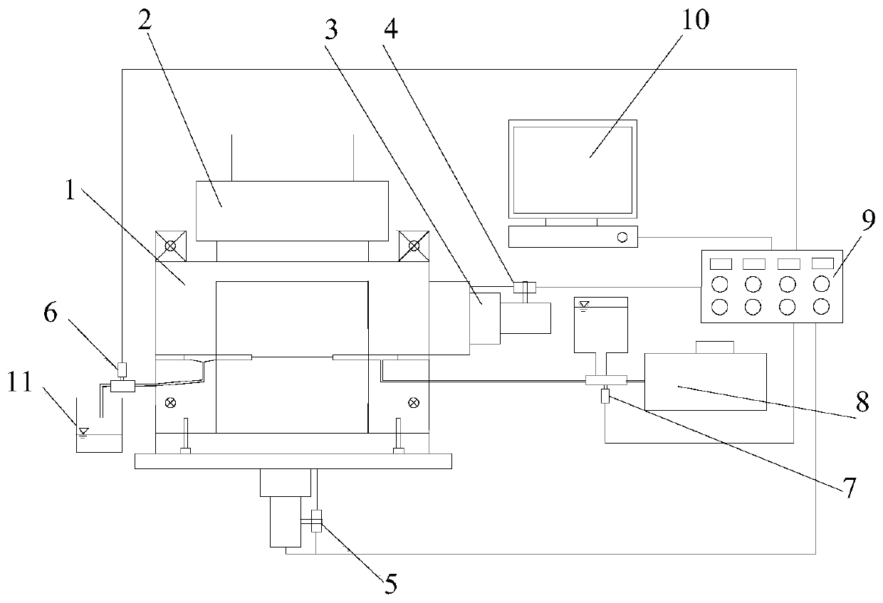
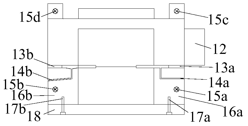
[0033] In a typical embodiment of the present invention, such as figure 1 As shown, a test device for visualizing the failure process of shear-seepage coupling is provided, including an upper shear box 12, a pad, a lower shear box, a pressure loading mechanism, a permeate loading mechanism, a sensor and a controller, and the upper shear box 12 The bottom end of the box 12 is attached to the spacer, and the bottom end of the spacer is attached to the lower shear box, that is, the upper shear box 12 is located at the upper end of the lower shear box, between the upper shear box 12 and the lower shear box. A spacer is provided, and a water inlet 14a and a water outlet 14b are provided on the side where the spacer is attached to the upper shear box 12 or the lower shear box. The permeate loading mechanism is connected to the water inlet 14a, and the pressure loading mechanism can push the upper shear box. The box 12 is used to cut the practice; the sensor is connected to the contr...

Embodiment 2

[0052] In a typical implementation of the present invention, a test method for visualizing the shear-seepage coupling failure process of non-penetrating joint rock mass is also provided, using the test device for visualizing the shear-seepage coupling failure process as described in Example 1 , including the following steps:

[0053] 1) Set up a test device for visualizing the shear-seepage coupling failure process as described in Example 1;

[0054] 2) Use rock-like materials to make non-penetrating jointed rock mass, and perform maintenance after the production is completed;

[0055] 3) Fix the upper shear box 12 and the lower shear box on the test bench, put the non-penetrating jointed rock mass sample, and conduct the shear-seepage coupling test.

[0056] The main components of the rock-like material are gypsum and cement, which are mixed evenly with water in a certain proportion, put into the corresponding mold to complete the sample production, and then the sample can b...


PUM


Abstract

The invention discloses a visual test device and method for a shear-seepage coupling failure process and belongs to the field of teaching experiment instruments, and a test basis can be provided for researching a failure mechanism of a rock bridge under shear seepage coupling effect under the condition of high seepage force; the device comprises an upper shearing box, a cushion block and a lower shearing box, wherein the upper shearing box is located at an upper end of the lower shearing box, the cushion block is arranged between the upper shearing box and the lower shearing box and provided with a water inlet and a water outlet, and side plates of the upper shearing box and the lower shearing box are provided with transparent structures for observation.

Description

technical field [0001] The invention belongs to the field of teaching experiment instruments, and in particular relates to a test device and method for visualizing the shear-seepage coupling failure process. Background technique [0002] The statements herein merely provide background information related to the present invention and do not necessarily constitute prior art. [0003] In projects such as petroleum mining, water conservancy and hydropower, coal mine production, and traffic slopes, groundwater has an important impact on the stability of rock mass engineering. The failure and instability of a large number of engineering rock masses is usually caused by the shear sliding of certain structural surfaces in the rock mass under the action of loads or changes in conditions to generate new shear sliding surfaces, and the groundwater slides on this The formation of the surface has an important influence. For non-penetrating jointed rock mass, due to the existence of roc...

Claims


Application Information

Patent Timeline
Patent Type & Authority Applications(China)
IPC IPC(8): G01N3/12G01N3/24G01N3/06
CPCG01N3/068G01N3/12G01N3/24G01N2203/0026G01N2203/0048G01N2203/0242G01N2203/0652
Inventor 杨旭旭李丽超孙盼盼孙德康乔卫国
Owner SHANDONG UNIV OF SCI & TECH
Why Eureka
Try Eureka