Light display method and device

A ray and ray tracing technology, applied in the computer field, can solve the problems of high debugging cost, difficult debugging of ray tracing algorithm, and inability to observe the 3D image construction process intuitively, so as to reduce debugging cost and reduce debugging difficulty.

Pending Publication Date: 2021-06-15
北京天空卫士网络安全技术有限公司
View PDF0 Cites 0 Cited by
  • Summary
  • Abstract
  • Description
  • Claims
  • Application Information

AI Technical Summary

Problems solved by technology

[0004] In the existing methods involving ray tracing technology, since the final construction is a three-dimensional image, the light rays in the process of constructing the three-dimensional image are invisible, and the construction process of each pixel in the three-dimensional image cannot be observed intuitively, and The ray tracing algorithm cannot be debugged before the 3D image construction is completed, which makes the debugging of the ray tracing algorithm difficult and expensive

Method used


Image

  • Light display method and device
  • Light display method and device
  • Light display method and device

Examples


Embodiment Construction

[0047] Exemplary embodiments of the present invention are described below in conjunction with the accompanying drawings, which include various details of the embodiments of the present invention to facilitate understanding, and they should be regarded as exemplary only. Accordingly, those of ordinary skill in the art will recognize that various changes and modifications of the embodiments described herein can be made without departing from the scope and spirit of the invention. Also, descriptions of well-known functions and constructions are omitted in the following description for clarity and conciseness.

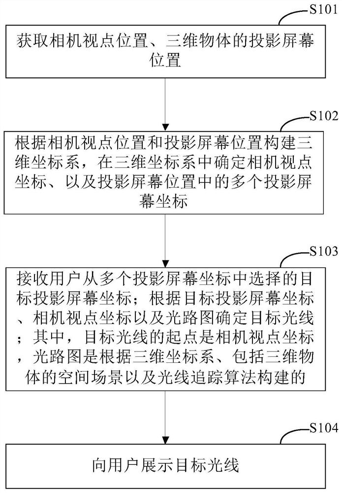
[0048] figure 1 It is a schematic diagram of the main flow of the light display method provided according to the first embodiment of the present invention; as figure 1 As shown, the light display method provided by the embodiment of the present invention mainly includes:

[0049] Step S101, acquiring the position of the viewpoint of the camera and the position of the pro...


PUM


Abstract

The invention discloses a light display method and a device, and relates to the technical field of computers. A specific embodiment of the method comprises the following steps: acquiring a camera viewpoint position and a projection screen position of a three-dimensional object; constructing a three-dimensional coordinate system according to the camera viewpoint position and the projection screen position, and determining a camera viewpoint coordinate in the three-dimensional coordinate system and a plurality of projection screen coordinates in the projection screen position; receiving a target projection screen coordinate selected by the user from the plurality of projection screen coordinates; determining target light according to the target projection screen coordinate, the camera viewpoint coordinate and the light path diagram; wherein the starting point of the target light is a camera viewpoint coordinate, and the light path diagram is constructed according to the three-dimensional coordinate system, a space scene comprising a three-dimensional object and a light tracing algorithm; and displaying the target light to the user. According to the embodiment, the technical effects of reducing the debugging difficulty of the ray tracing algorithm and reducing the debugging cost are achieved.

Description

technical field [0001] The present invention relates to the field of computer technology, in particular to a light display method and device. Background technique [0002] Ray tracing is a method of rendering three-dimensional images on a two-dimensional screen and is widely used in computer games and animation, television and DVD production, and film productions. In ray tracing techniques, the path of each ray consists of multiple straight lines, almost always involving reflection, refraction and shadowing effects from the origin to the scene. In animation, the position and direction of the straight portion of each ray is always changing, so each ray is represented by a mathematical equation that defines the ray's spatial path as a function of time. Each ray is assigned a color based on the pigment, or color, of objects in the scene it passes through before reaching the screen. Every pixel on the screen corresponds to every ray of light that can be traced back to the sour...

Claims


Application Information

Patent Timeline
Patent Type & Authority Applications(China)
IPC IPC(8): G06T15/06
CPCG06T15/06
Inventor 王毅刘佩葛国峰
Owner 北京天空卫士网络安全技术有限公司
Why Eureka
Try Eureka