
Full-coverage path planning method for unmanned aerial vehicle

A path planning, UAV technology, applied in vehicle position/route/altitude control, non-electric variable control, instruments, etc., can solve the problems of complex UAV full coverage path planning, low precision, and large error.

Inactive Publication Date: 2020-08-25
王方正
View PDF0 Cites 4 Cited by
  • Summary
  • Abstract
  • Description
  • Claims
  • Application Information

AI Technical Summary

Problems solved by technology

[0004] For this reason, the embodiment of the present invention provides a UAV full-coverage path planning method to solve the problems of complex, large error and low precision in the existing UAV full-coverage path planning.

Method used


Image

  • Full-coverage path planning method for unmanned aerial vehicle
  • Full-coverage path planning method for unmanned aerial vehicle
  • Full-coverage path planning method for unmanned aerial vehicle

Examples


Embodiment 1

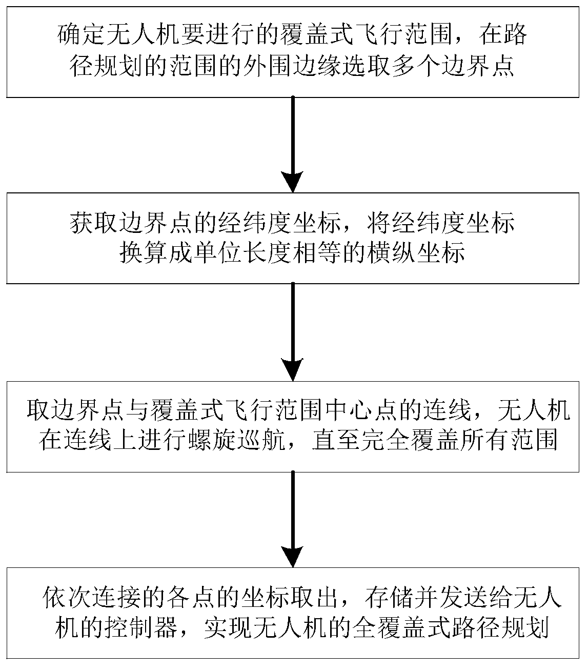
[0040] refer to figure 1 , this embodiment discloses a UAV full-coverage path planning method, the method is:

[0041] Determine the coverage flight range to be carried out by the UAV, and select multiple boundary points on the outer edge of the path planning range;

[0042] Obtain the latitude and longitude coordinates of the boundary point, and convert the latitude and longitude coordinates into horizontal and vertical coordinates with equal unit length;

[0043] Take the connection line between the boundary point and the center point of the covered flight range, and the UAV performs spiral cruise on the connection line until it completely covers all the range;

[0044] The coordinates of each point connected in sequence are taken out, stored and sent to the controller of the drone to realize the full-coverage path planning of the drone.

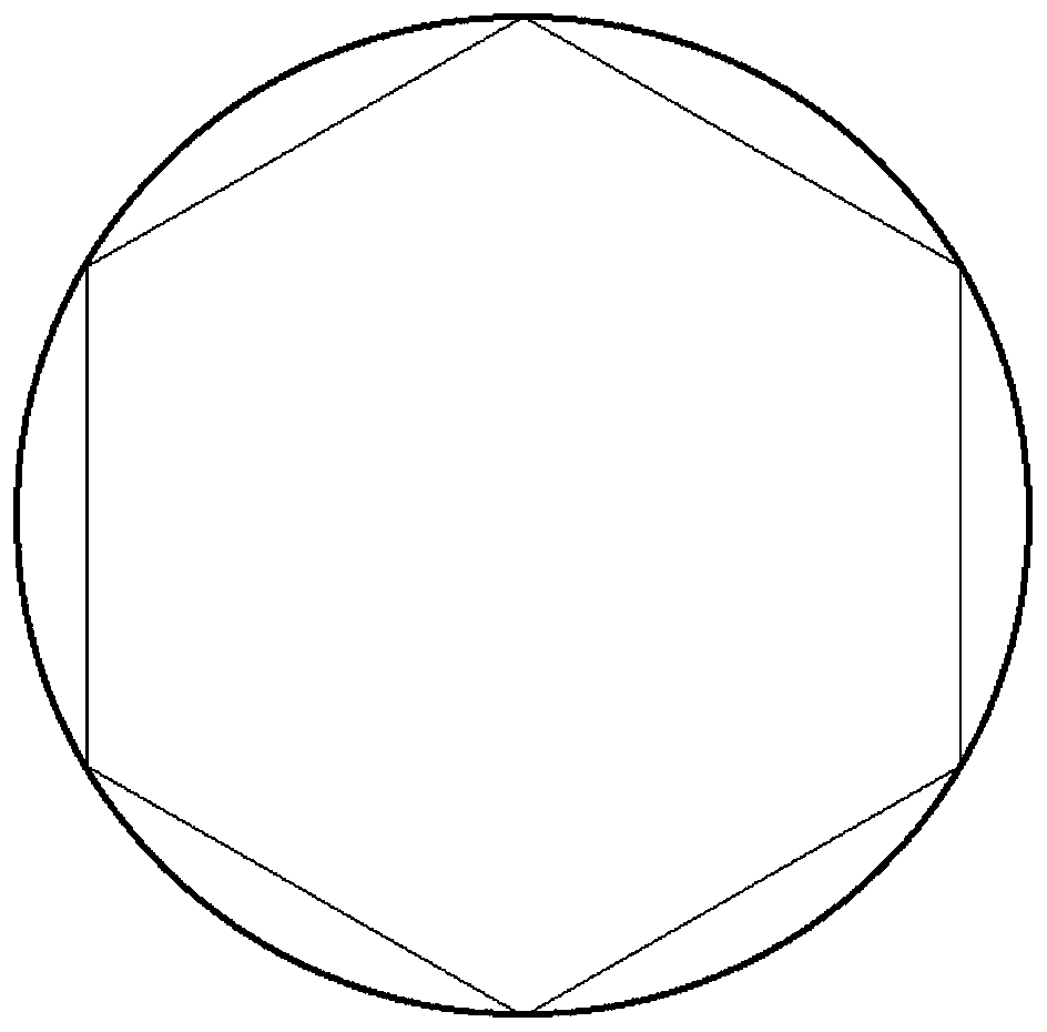
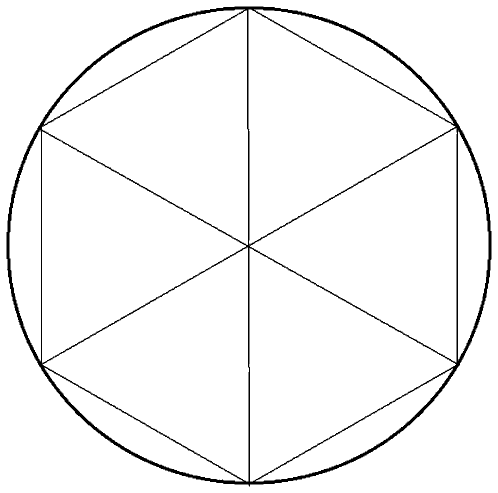
[0045] refer to figure 2, the perimeter of the covering flight range to be carried out by the UAV is s meters, a boundary point is se...

Embodiment 2

[0058] refer to Figure 6 , this embodiment discloses a full-coverage path planning method for unmanned aerial vehicles. The perimeter of the covered flight range to be carried out by the unmanned aerial vehicle is set to be s meters, and a boundary point is selected every x meters distance, and a total of i Points, obtain the latitude and longitude coordinates of i points through the positioning system, (j1, w1), (j2, w2)...(ji, wi), and then convert the latitude and longitude coordinates into horizontal and vertical coordinates with equal unit length, k∈( 1~i),

[0059] x k = j k ×cosw k ,

[0060] the y k =w k

[0061] Connect two adjacent points into a line segment (that is, the boundary line), and get the expression

[0062] I1: If x1

[0063] y=a 1 ×x+b 1

[0064] I2: If x2

[0065] y=a 2 ×x+b 2

[0066] ....., ...


PUM


Abstract

The embodiment of the invention discloses a full-coverage path planning method for an unmanned aerial vehicle. The method comprises steps of determining a coverage flight range to be carried out by the unmanned aerial vehicle, and selecting a plurality of boundary points at a peripheral edge of a path planning range; obtaining longitude and latitude coordinates of the boundary points, and converting the longitude and latitude coordinates into horizontal and vertical coordinates with equal unit length; taking connecting lines of the boundary points and the center point of the coverage type flight range, and performing spiral cruise on the connecting lines by the unmanned aerial vehicle till all ranges are completely covered; or connecting two adjacent boundary points to obtain a transversemovement length of the selected range, taking an equal division point on the transverse movement length to be connected with the boundary points to obtain intersection points, and connecting the intersection points to perform snake-shaped cruise till all the ranges are covered; and taking out coordinates of the points connected in sequence, storing the coordinates and sending the coordinates to acontroller of the unmanned aerial vehicle to realize full-coverage path planning of the unmanned aerial vehicle. The method is advantaged in that the method solves problems that an existing unmanned aerial vehicle is complex in full-coverage path planning, large in error and low in precision.

Description

technical field [0001] Embodiments of the present invention relate to the field of unmanned aerial vehicle control, and in particular to a full-coverage path planning method for unmanned aerial vehicles. Background technique [0002] In many scenarios, the UAV is required to perform full-coverage cruise within a certain fixed range, that is, the flight trajectory can fill the entire area. For example: use a drone to spray pesticides on a certain range of crops, and the work will be completed only after the entire area is sprayed. [0003] At present, there are mainly two methods for full-coverage path planning. One is to manually plan routes. The disadvantage is that for a large area, when the lines are dense, manual planning is too cumbersome and has large errors; In the process of planning the route by yourself, the disadvantage is that there is a large uncertainty, and it is impossible to accurately predict the walking route of the drone. Contents of the invention [...

Claims


Application Information

Patent Timeline
IPC IPC(8): G05D1/10G01C21/20
CPCG01C21/20G05D1/101
Inventor 王方正冀杰
Owner 王方正
Learn More