Magnetic coupling type distribution network mechanical load switch cabinet

A load switchgear, magnetic coupling technology, applied in the direction of pull-out switchgear, switchgear, switchgear parts, etc., can solve the problems of inconvenient production and maintenance, complicated assembly and maintenance, complex structure, etc., to achieve convenient maintenance, The effect of convenient later maintenance and compact cabinet structure

Pending Publication Date: 2020-08-25
CHANGZHOU BORI ELECTRIC POWER AUTOMATION EQUIP +2
View PDF0 Cites 3 Cited by
  • Summary
  • Abstract
  • Description
  • Claims
  • Application Information

AI Technical Summary

Problems solved by technology

However, the existing load switchgear has a complex structure, cumbersome assembly and maintenance, which brings great inconvenience to production and later maintenance

Method used


Image

  • Magnetic coupling type distribution network mechanical load switch cabinet
  • Magnetic coupling type distribution network mechanical load switch cabinet
  • Magnetic coupling type distribution network mechanical load switch cabinet

Examples


Embodiment Construction

[0024] In order to make the content of the present invention more clearly understood, the present invention will be further described in detail below based on specific embodiments and in conjunction with the accompanying drawings.

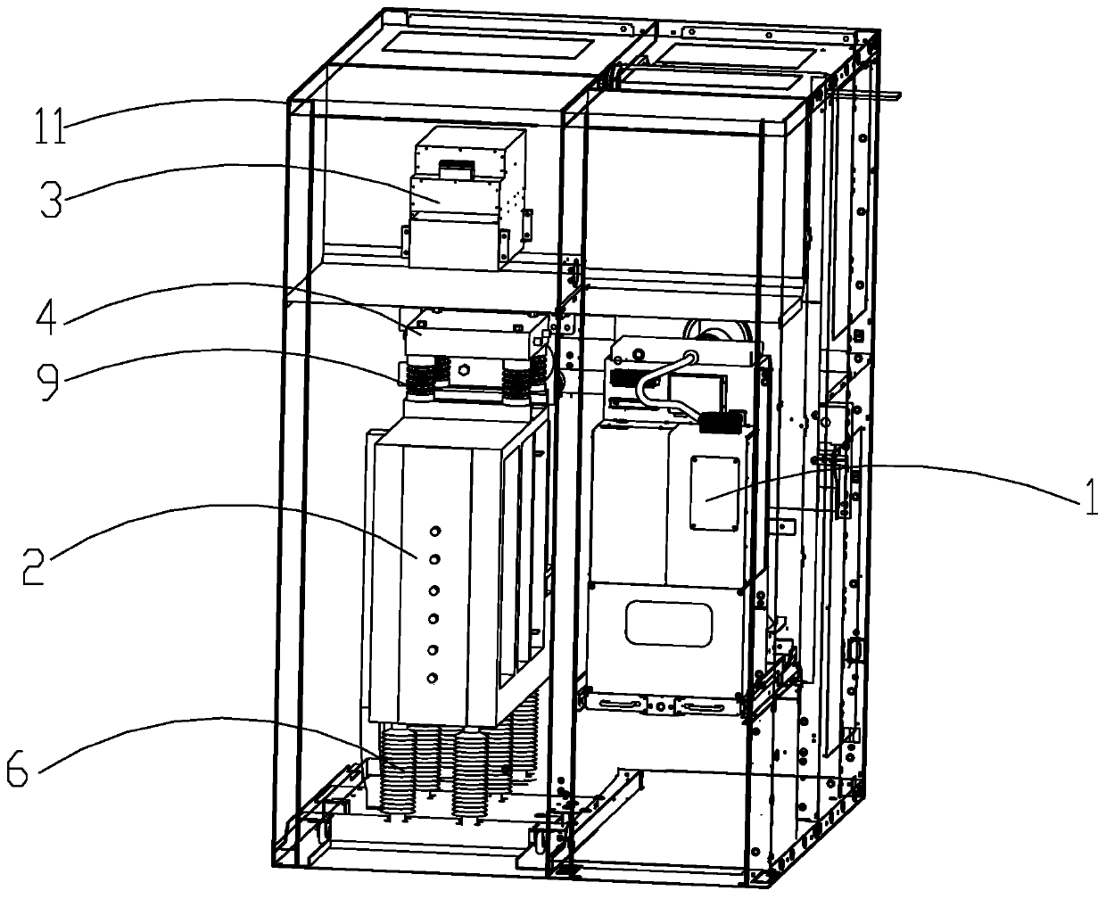
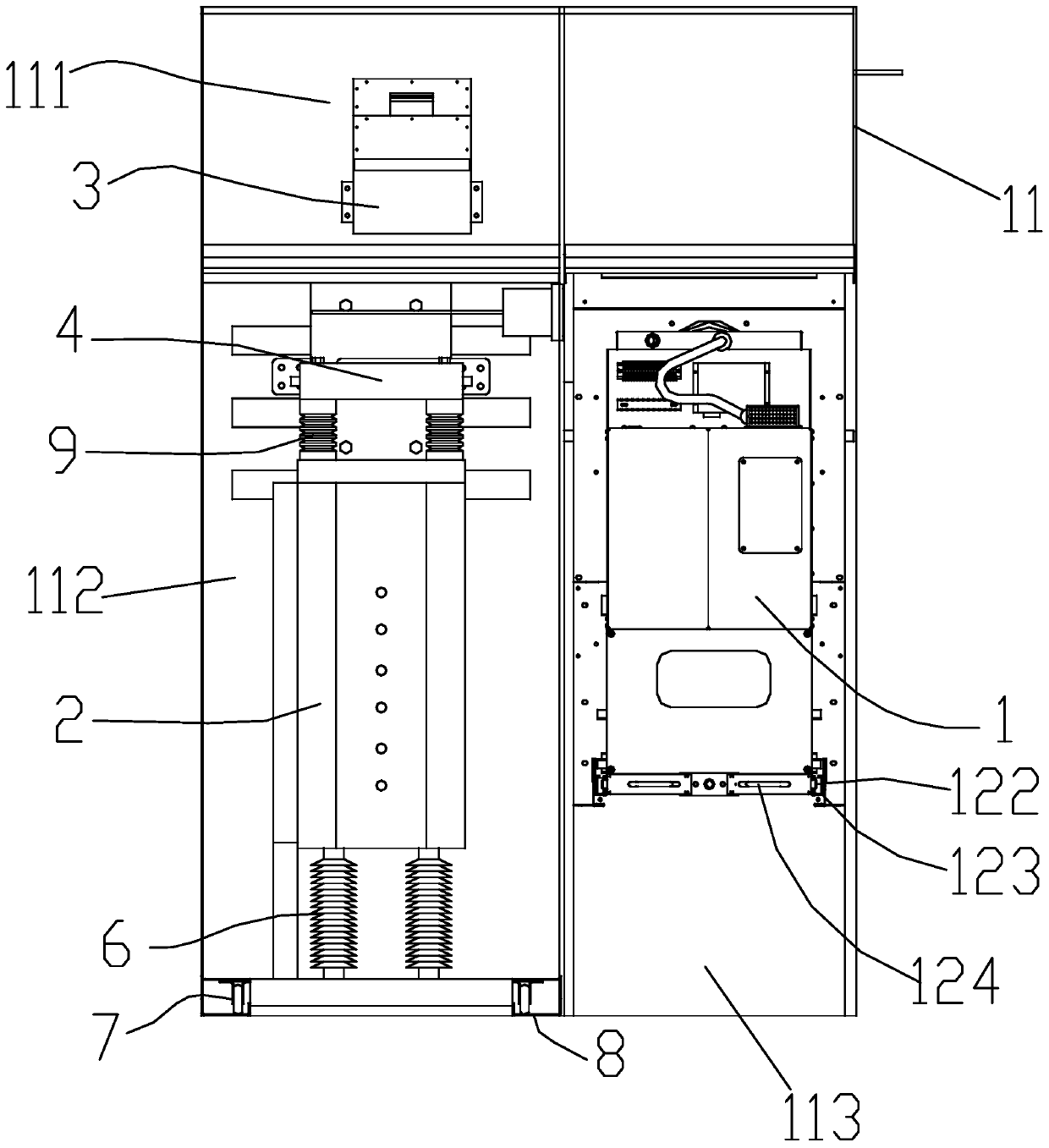
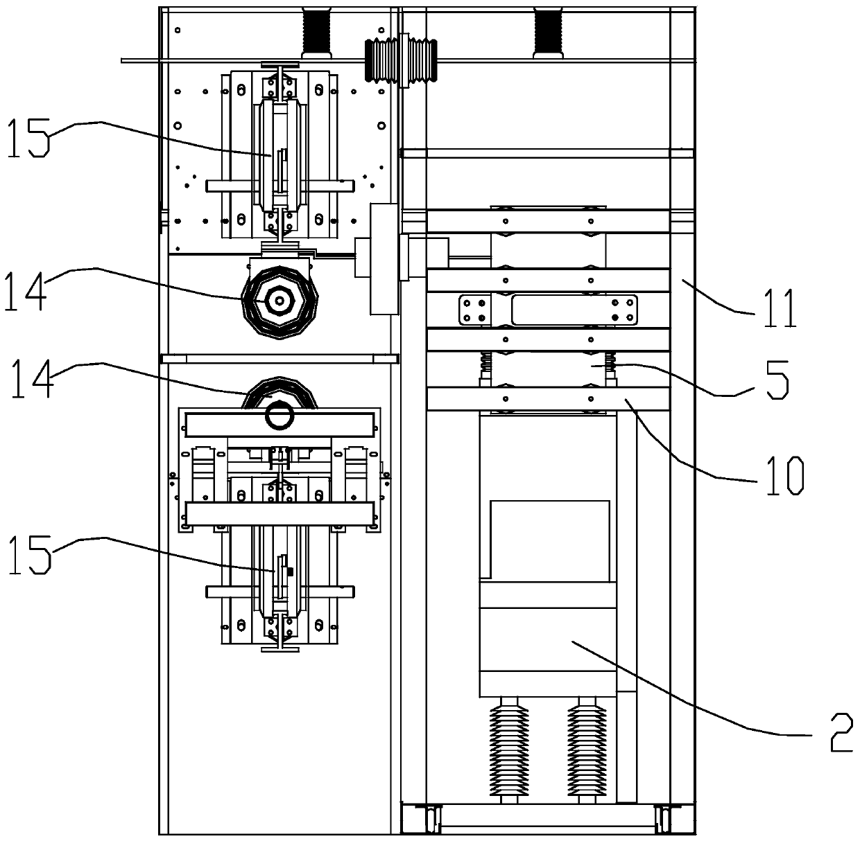
[0025] Such as Figure 1-6 As shown, a magnetic coupling type distribution network mechanical load switch cabinet includes a cabinet body 11. The cabinet body 11 includes a device room 111, a valve room 112 and a handcart room 113. The device room 111 is located above the valve room 112. The vehicle chamber 113 is located on the side of the device chamber 111 and the valve chamber 112. The device chamber 111 is provided with a magnetic coupling trigger circuit 3, and the valve chamber 112 is provided with a transfer branch 2 and a magnetic coupling reactor 4. The transfer branch 2 can be placed in the valve In and out of the chamber 112, the magnetic coupling reactor 4 is fixed on the top of the transfer branch 2, the magnetic coupling trigger circ...


PUM


Abstract

The invention discloses a magnetic coupling type distribution network mechanical load switch cabinet which comprises a cabinet body, and the cabinet body comprises a device chamber, a valve chamber and a handcart chamber. The device chamber is positioned above the valve chamber; the handcart chamber is positioned on the side surfaces of the device chamber and the valve chamber; a magnetic couplingtrigger loop is arranged in the device chamber; a transfer branch and a magnetic coupling reactor are arranged in the valve chamber, the transfer branch can go in and out of the valve chamber, the magnetic coupling reactor is fixed at the top of the transfer branch, the magnetic coupling trigger circuit is connected with the magnetic coupling reactor through a copper bar, a quick switch handcartand a contact box are arranged in the handcart chamber, and the quick switch handcart is pushed into the handcart chamber to be connected with the contact box in an inserted mode. The invention provides the magnetic coupling type distribution network mechanical load switch cabinet which is simple and compact in structure and convenient to assemble and maintain in the later period.

Description

technical field [0001] The invention relates to a magnetic coupling type distribution network mechanical load switch cabinet. Background technique [0002] At present, with the development of DC power supply (distributed power supply and energy storage technology) and DC load (connection of different types of loads such as electric vehicles to the grid) in recent years, the development of DC power distribution technology has been promoted. Compared with AC power distribution, DC power distribution technology has the characteristics of large transmission power, low power loss, asynchronous operation, and high power supply reliability. Since the breaking current of 10kV DC load switch is DC, there is no natural zero-crossing point. Therefore, when breaking the rated current, it is necessary to manually create a zero-crossing point to realize arc extinguishing and complete rated current breaking. At present, based on the fast switch opening, the magnetic coupling coil couples ...

Claims


Application Information

Patent Timeline
Patent Type & Authority Applications(China)
IPC IPC(8): H02B11/167H02B11/26H02B11/02
CPCH02B11/02H02B11/167H02B11/26
Inventor 姚宁吴中友王智勇陈新李德召吕玮陈羽
Owner CHANGZHOU BORI ELECTRIC POWER AUTOMATION EQUIP
Why Eureka
Try Eureka