Data machine room temperature inspection robot arranged at top of cabinet and method

A technology for inspection robots and data computer rooms, applied to chemical instruments and methods, cleaning methods using tools, thermometers, etc., can solve problems such as the system occupies a large space, cannot cover the top of the cabinet, and the installation process is complicated

Pending Publication Date: 2020-08-28
NANJING UNIV OF TECH
View PDF2 Cites 1 Cited by
  • Summary
  • Abstract
  • Description
  • Claims
  • Application Information

AI Technical Summary

Problems solved by technology

[0003] In recent years, the research on the temperature detection technology of the data computer room has made great progress, and related technologies have also emerged for the practical application of the temperature detection of the data computer room. The detection method described in the patent uses a convenient reference point on the ground as the origin to establish the temperature distribution spatial coordinates of the data room; multiple detection points are evenly set in the space, and the temperature value of each detection point needs to be installed. The detection device, whose installation process is complicated, and the system takes up a large space, is not suitable for the transformation of the existing computer room; the patent CN201721518504 proposes a temperature detection and control device for the computer room. The detection system of this patent includes a first outdoor temperature sensor and There are multiple second temperature sensors installed in different areas of the room. The number of temperature sensors installed in the room is too large and difficult to control. The detection points are more focused on the middle and lower areas of the cabinet and cannot cover the top of the cabinet.

Method used


Image

  • Data machine room temperature inspection robot arranged at top of cabinet and method
  • Data machine room temperature inspection robot arranged at top of cabinet and method

Examples


Embodiment Construction

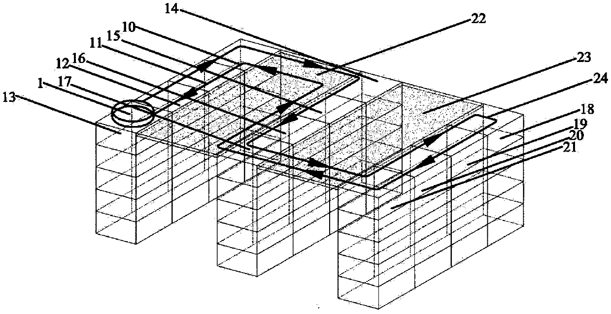
[0028] like figure 1 As shown, a data room temperature inspection robot arranged on the top of the cabinet mainly includes: 1. robot, 10. first cabinet, 11. second cabinet, 12. third cabinet, 13. fourth cabinet, 14. Five cabinets, 15. Six cabinets, 16. Seventh cabinets, 17. Eighth cabinets, 18. Ninth cabinets, 19. Tenth cabinets, 20. Eleventh cabinets, 21. Twelfth cabinets, 22. No. A connection board, 23. a second connection board, 24. a moving route of the robot.

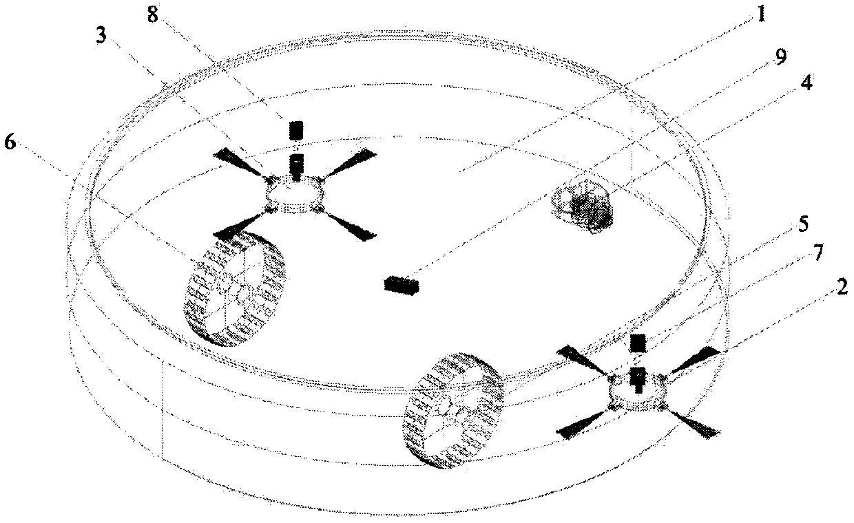
[0029] like figure 2 As shown, the first robot hair brush 2 and the second robot hair brush 3 are respectively located on both sides of the front of the bottom of the robot 1, the robot universal wheel 4 is located at the front of the bottom of the robot 1, and the first robot power wheel 5 and the second robot power wheel 6 are respectively located on both sides of the rear of the bottom of the robot 1, the first retractable spring temperature sensor 7 and the second retractable spring temperature sensor 8 are ...


PUM


Abstract

The invention discloses a data machine room temperature inspection robot arranged at the top of a cabinet, and belongs to the field of data machine room thermal environment detection. The problems that the temperature of a data room space is difficult to monitor and the dust accumulated at the top of the cabinet is difficult to clean are solved. The data machine room temperature inspection robot mainly includes a robot body (1), a first robot brush (2), a robot universal wheel (4), a first robot power wheel (5), a first retractable spring temperature sensor (7), an infrared temperature sensor(9), a first cabinet (10), a first connecting plate (22) and the like. The telescopic temperature sensors are installed on the two sides of the robot body to measure the temperature distribution of front and rear entrances and exits of the cabinet, the infrared temperature sensor is combined to measure the temperature distribution at the top of the cabinet, the robot moves at the top of the cabinet, the space for additionally arranging a temperature detection system is saved, and the dust accumulated at the top of the cabinet is cleaned.

Description

technical field [0001] The invention relates to a data machine room temperature inspection robot and method arranged on the top of a cabinet, belonging to the field of data room thermal environment detection. Background technique [0002] Data centers (computer room systems) generally have a large number of IT equipment (such as servers, network equipment, etc.) and infrastructure equipment (such as air conditioners, power equipment, etc.). With the expansion of the data center system, its supporting IT equipment is also increasing, and the computer room has become an important part of each major unit. The energy consumption of the data center system is very large. The energy consumption of a standard large-scale data center is currently equivalent to a small city with hundreds of thousands of people. While consuming electric energy, it will release heat energy and cause temperature accumulation. If it cannot dissipate heat in time, it will Cause the computer room to shut d...

Claims


Application Information

Patent Timeline
Patent Type & Authority Applications(China)
IPC IPC(8): B25J5/00B25J9/16B25J13/08B25J11/00G01J5/00G01J5/02G01K13/00B08B1/00
CPCB25J5/007B25J9/1666B25J9/1676B25J13/087B25J11/00G01J5/0096G01J5/0205G01K13/00B08B1/002
Inventor 许鑫洁王瑜成峰鲍俊牛晓熠刘金祥
Owner NANJING UNIV OF TECH
Why Eureka
Try Eureka